Electron Ionization Sources: The Basics
The ion source is the heart of the mass spectrometer. In the ion source, ions are created from gas-phase neutral sample molecules, or preformed ions are extracted from solutions, and then sent into the mass analyzer of the instrument. The electron ionization (EI) source was the first source widely used for organic mass spectrometry (MS), and design, development, and optimization of this source are all the result of the work of many of the early pioneers of MS.


The sensitivity of a mass spectrometer (the source combined with the remainder of the instrument, but sometimes also the source itself) is defined strictly in units of C/μg, where C represents the charge in coulombs carried by ions that can be created from 1 μg of sample introduced to the source. The sensitivity of any MS measurement is predicated first upon instrument sensitivity (including factors such as source performance, mass analyzer transmission, and ion detection efficiency), but also expands to include sample preparation, signal-to-noise discrimination, and matrix effects in real samples. The central position of source performance in this scheme should be clear. For EI sources, source design and operational details directly affect source performance. It is useful then to broadly consider the 50-year history of the EI source in terms of sensitivity, and its optimization, but also to include all the other factors that go into the design and construction of an ion source.
We begin with the essential elements of the EI source. Essential components of an EI source assembled into the basic layout can be found in schematics in introductory texts or manufacturer's literature on the web. Often it seems that short shrift is given to the EI source, and details of design and optimization are overlooked in the fact that the EI source is so common. Lack of current research literature on the design of the EI source reflects the long history of successful development of this source for organic analysis, the tendency for design studies to be completed now in conjunction with instrument manufacture (and therefore to be proprietary), and the attention given to new ionization methods. However, more specialized applications of the EI source often require revisiting these fundamental design parameters; examples of these applications include portable instruments and instruments for analysis in extreme environments. Importantly, an appreciation of the factors considered in the design of the EI source, the balances reached in accord with the transfer of sample molecules into the source, and the transfer of ions out of it informs our designs and evaluations of other ionization sources. In this column, we begin a brief overview of some of these factors and balances; then in the next column, we revisit some of the "older" scientific literature and hopefully enlighten the understanding of source design for mass spectrometers.
The basic function of an EI source is to create ions from neutral gas-phase sample molecules M, according to the equation:
Mo + e-filament → M+ + e-molecule + e-filament
where the electrons causing molecular ionization are emitted usually from a heated metal filament. In most EI sources, the filament is made of tungsten or rhenium, fabricated as a wire, a coil, or sometimes a ribbon. Figure 1 is a photograph of such a filament, and the coiled structure can be clearly seen. The coil (or multiple ribbons) provides a greater surface area from which thermionic emission of electrons can occur. Specialized materials that have been used, often in the higher operating pressures of residual gas analyzers, include thoriated iridium (thoria coated onto a supporting iridium wire) and yttriated iridium. Other specialized applications demand other filament materials; these are compiled in Manura's authoritative texts on the subject (1,2). Tungsten is cheapest, but it produces carbon dioxide by reactions of hydrocarbons at the heated metal surface. This is not usually an issue in organic MS, which usually does not scan to that low of a mass or attach high interpretive value to the ion at m/z 44, but the interference is something to be aware of in other applications. Rhenium filaments produce carbon dioxide to a lesser extent due to the lower work function of rhenium and the resultant lower operating temperature. However, rhenium filaments emit stable rhenium oxide negative ions that can be a potential mass interference in some analyses.

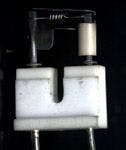

Figure 1: Photograph of a coiled filament used in an electron ionization source. Look closely to see the ion burn behind the filament. Cropped from an original photograph taken by Frederick Strobel, Manager of the Mass Spectrometry Facility at Emory University, and used with permission.
The filament is heated by a robust power supply that passes current sufficient to heat the filament to its operating temperature. Because the power supply provides 3–4 amperes at 70 V relative to ground (more on that later), great care must be taken to avoid personal contact with the output. The current passage raises the temperature of the filament to a point at which the work function of the heated metal is exceeded, and electrons are then released from the surface of the metal in a process of thermionic emission. Remember that the work function is defined simply as the minimum amount of energy required to remove an electron from the surface of a metal. The relationship between work function and temperature is described in "older" research literature (3,4) and is summarized in the Richardson–Dushman equation (5,6), which relates the emitted current density to the work function (W) and temperature (T) of the emitting material:
js = A T2 e(–W/kT)
where jS is the current density of the emission (mA/mm2 ), A is Richardson's constant (approximately 1202 mA/mm2 K2 ), T is temperature (K), W is the work function of the cathode material (J), and k is the Boltzmann constant (1.38066 × 10⁻²³ J/K).
The filament operates in a vacuum such that the heated metal does not immediately oxidize, become brittle, and fracture, much as an incandescent lightbulb filament will burn out in a few seconds if the surrounding glass envelope that maintains the inert atmosphere is breached. The equation that describes thermionic emission assumes emission into a vacuum, and so the fit of theoretical equation to experimental results is good (subject to corrections such as the Schottky effect). Remember that the pressure of sample molecules in the EI source will be about 10-6 torr, or about the same as the base pressure of the instrument itself. In a chemical ionization (CI) source, as you recall from previous columns, the pressure of the reagent gas in the source is about 1 torr. Resultant changes in basic design and operation of the source, including the filament, to accommodate this higher operating pressure are discussed in an upcoming parallel series of columns on the design and operation of the CI source.
Stable electron emission from a metal filament (as clear from the equation above) requires a few minutes of operation to reach a thermal "equilibrium," or more accurately, a constant temperature at which the flux of emitted electrons becomes constant. This period is reached when a balance is achieved between heat generation due to the passage of the filament current and loss of heat to the source block. The current passed through the filament heats not only the wire itself, but through radiation and some convection, it also heats surrounding metal. The source block is the metal "container" into which gas-phase sample molecules and electrons are introduced and contained, and from which ions are extracted into the mass analyzer. The internal volume of a typical EI source block is on the order of 1 mL; for miniaturized instruments it can be less. It is instructive to calculate the mean free path of an ideal gas at the pressure and temperature at which the EI source operates and compare that value with the dimensions of the source block itself. The source block is heated by radiative emission from the filament and by dedicated source heaters as well to minimize the time required to reach an equilibrium operating temperature and to maintain source cleanliness. The normal operating temperature is 180–220 °C, depending on what sorts of samples are being brought into the source.
Why is the source block heated? Recall that hot metal often catalyzes organic sample decomposition, so it seems that this would be a bad idea from the start. In this case, however, the source is heated to prevent condensation of gas-phase sample molecules onto the "cold" metal walls, leading to source contamination through sample cross talk, as well as a generally "dirty source" through condensation of the background organic vapors always present in the instrument. Sample cross talk occurs when the sample molecules adsorb on the surface, remain there for some time that becomes similar to the time between the introduction of the subsequent sample, and then desorb from the surface. The ideal situation is that neutral gas-phase sample molecules are introduced into the source and are promptly ionized or pumped away out of the source, with no residue. When sample molecule introduction is via a gas chromatograph, and peaks are only a few seconds wide and often closely spaced, sample cross talk can decrease the apparent separation resolution of the chromatography.
After electrons are emitted from the filament, they must pass through the internal volume of the ion source, (hopefully) ionizing any gas-phase neutral molecules found there. Ideally, the electron beam should uniformly illuminate the entire source volume. Thus, the bigger the emitting surface, the more likely that this ideal situation can be realized. In classical electron ionization, the source filament (and its power supply) is held at–70 V relative to the ground potential (zero volts) of the metal block of the ion source. An imposed acceleration potential between the ion source and the mass analyzer only shifts the frame of reference, but does not shift the filament–source potential difference. Simplistically, electrons released from the filament are repelled from the wire and attracted to the ground potentials of the surrounding block. Because the electrons are accelerated through a potential of 70 V, their velocity can be calculated. As described previously, a 70 V kinetic energy for the electrons represents a plateau region in which small changes in the velocity do not lead to large changes in the ionization efficiency for organic molecules.
Of course, the design of the source is usually a bit more complicated than the simple diagrams in introductory texts might indicate. The filament can be inside the source block, or, to facilitate replacement when the filament eventually fails, the filament is usually physically located outside the source block, attached to it by insulating stand-offs. Small holes are drilled in the metal of the ion source block between the filament and the interior (sometimes called the ion volume). From an inside-out perspective, the electron entrance holes are uniformly illuminated with electrons, which enter the interior volume of the ion source with 70 V kinetic energy. In some designs, a V-shaped repeller plate located behind the filament further increases the flux of electrons emitted from the filament that enter the source. An independent variable voltage is determined empirically to maximize the production of ions from the source under the usual operating conditions.
The filament current is measured at a collector located on the side of the ion source opposite from the electron entrance holes. The collector can be biased at a slight positive potential or can itself operate at ground potential. The collector does not intercept all electrons that enter the source, and the number of electrons collected will also reflect the ionization process (equation 1). But because the geometry is constant, the fraction of electrons collected is fixed, and the protocol is such that for standard EI operations, a collector value of about 150 μA is set. Usually this set value is part of a feedback circuit that changes the current driving the filament to maintain a constant collector current.
Designers of instruments and ion sources want to increase the chances of electron–molecule interaction. We can accomplish this by increasing the number of electrons, the illuminated volume, or the electron path length inside the ion source. These possible approaches must be balanced against the general rule that the EI source should be compact. In a compact source, gas-phase samples are introduced and removed in a short time, concordant with sequential sample peaks introduced from a gas chromatograph in which the peaks may be only a few seconds wide and a few seconds apart. A compact source is easier to pump and easier to design as a point source for extraction of ions into the mass analyzer. Finally, and not to put too fine a point on it, a compact source is smaller. In some applications, size is critical, but in others, it is simply the associated scaling with materials and power supplies that becomes the balancing factor. With any given size of ion source, only a certain flux of electrons can be achieved based on filament design and ion optics (including space charge, a topic covered in a previous column). So while electron flux can be increased, the flux that leads to a collector current of 150 μA represents a balance of many factors.
The second approach, to increase the illuminated volume inside the source, has been implemented using a higher number of electron entrance apertures or using multiple filaments. But this approach ultimately reaches the same realistic limits as the straightforward first approach that simply advocates more electrons.
Optical spectroscopy will recognize the third approach as the EI source equivalent of increasing the optical path length in an absorbance cell. Electron mirrors can be configured, and multipass electron paths can be used. But a simpler and more elegant approach is to use a source magnet. This is not the magnet of the mass analyzer in a sector mass spectrometer. The source magnet is a small, permanent magnet fitted to the source that causes the electrons to follow a spiral path within the ion volume, effectively increasing the path length and increasing the chances for sample molecule–electron interaction. The strength of the magnet is such that electron trajectories are suitably changed but any of the more massive molecular ions formed (remember that the mass of an electron is much smaller than the mass of a proton) are not perturbed, and sample ion extraction is not affected.
We end this column with a fundamental consideration of the efficiency of an EI source. We consider an EI source sensitivity specified as 1 × 10⁻⁷ C/μg of methyl stearate introduced into the source (this is a reasonable number for instruments of moderate performance). Detail-oriented readers immediately ask about the time associated with that sample introduction. Is it 1 s? 10 s? 100 s? These times represent the period over which the ion current produced is integrated. In gas chromatography–MS, a 1-s period would be desirable, but for a static headspace application, longer times might be appropriate. Further, we would need to know whether the ion current is specified as measured for the sum over a mass range, or even for a particular ion. For methyl stearate and EI, the molecular ion of the compound at m/z 298 usually is specified. Given the molecular weight and Avogadro's number, the actual fraction of neutral sample molecules converted into molecular ions can be calculated. We will start with that answer at the beginning of the next column.
Kenneth L. Busch learned to spot-weld filaments onto support posts at an early age, and remembers why the chemical symbol for tungsten is W, and the associated debate about the name and the symbol. He also remembers his first musings about the chemical composition of the ion burns found in an electron ionization source; those secrets remain unrevealed until a future column. He can be reached at WyvernAssoc@yahoo.com
References
(1) J.J. Manura, The Mass Spec Source 27(1), 3–4 (2005).
(2) http://www.sisweb.com/portal/ms-filament-wire.htm
(3) S. Dushman, Rev. Mod. Phys. 2(4), 381–476 (1930).
(4) P.A. Redhead, J. Vac. Sci. Technol., A 16(3), 1394–1401 (1998).
(5) A.L. Smith and R. Breitwieser, J. Appl. Phys. 41(1), 463–467 (1970).
(6) Owen Willans Richardson was awarded the Nobel prize in Physics in 1928 for his work on thermionic emission. Saul Dushman was a research scientist at the General Electric Company. The Nobel prize lecture of Richardson is found here: http://nobelprize.org/physics/laureates/1928/richardson-lecture.pdf


Getting accurate IR spectra on monolayer of molecules
April 18th 2024Creating uniform and repeatable monolayers is incredibly important for both scientific pursuits as well as the manufacturing of products in semiconductor, biotechnology, and. other industries. However, measuring monolayers and functionalized surfaces directly is. difficult, and many rely on a variety of characterization techniques that when used together can provide some degree of confidence. By combining non-contact atomic force microscopy (AFM) and IR spectroscopy, IR PiFM provides sensitive and accurate analysis of sub-monolayer of molecules without the concern of tip-sample cross contamination. Dr. Sung Park, Molecular Vista, joined Spectroscopy to provide insights on how IR PiFM can acquire IR signature of monolayer films due to its unique implementation.


