Understanding Calibration for Glow Discharge Atomic Emission Spectrometry (GD-AES)
Spectrochemical analysis is a comparative technique; therefore, unknown samples are best analyzed against reference materials of similar composition.
GD-AES Calibration: General Considerations
Spectrochemical analysis is a comparative technique; therefore, unknown samples are best analyzed against reference materials of similar composition. Certified reference materials (CRM) and reference materials (RM) are used to establish the relationship between concentration or mass ratio and light intensity or instrument response under precisely controlled lamp parameters. LECO calibrations employ reference materials that are traceable to or certified by NIST or other internationally recognized certifying bodies (ISO Guide 31).
GD-AES: Lamp Source
LECO Glow Discharge uses a Grimm-style lamp for atomic emission spectrometry. It is a nonthermal, cathodic sputtering device that sputters material from the sample surface; available in 4 mm anode diameter with 15 mm o-ring vacuum seal and 2 mm diameter (obtainable in two versions: large lamp, 15 mm o-ring, vacuum seal; and small lamp, 7 mm o-ring, vacuum seal). The sample is externally mounted on the vacuum seal o-ring. Sputtering is initiated when a high negative potential is applied under conditions of a partial pressure that includes a controlled supply of an easily ionized gas (argon). Argon ions impinge on the surface of the specimen removing atoms and small atomic clusters which may be dissociated into individual atoms. When excitation of the atoms or less frequently of ionic species occurs, a photon of light is emitted at a wavelength characteristic of the element from which the excited particle originated.
GD-AES Calibration: Considerations for Bulk Analysis
Choice of calibrants is crucial in forming robust working curves. Sufficient specimens must be chosen to reliably satisfy the entire concentration range for every element to be determined. The calibrants are measured at three locations around the piece, at minimum, to incorporate the uncertainty of the specimen on the working curves.
Most working curves are linear over a long dynamic range of concentration. Curve linearity allows accurate extrapolation even outside of the limits of the calibration range.
Instrument response can be accurately measured on array detectors or photomultiplier tubes (PMT).
GD-AES Calibration: Considerations for Quantitative Depth Profile Analysis
Quantitative depth profile (QDP) is used to measure discreet layers or diffusion gradients from the surface into the substrate of a specimen. QDP employs a sputter rate corrected calibration using bulk reference materials. Strict control of voltage and current are required in order to maintain constant relationships between sputter rates of different materials. Data is collected simultaneously on all channels as intensity versus time. Depth is calculated using material density and lamp geometry. There is no need for material specific thickness standards or expensive auxiliary equipment such as a profilometer in order to create a calibration.
Sputter rate is a material constant. If Sample A has a sputter rate of 4 and Sample B sputters has a sputter rate of 1, Sample A would yield a signal four times higher than Sample B for the same concentration of a given analyte.
Sputter rate corrected calibration is required to create usable working curves. Signal intensity for an element is proportional to the concentration in the plasma rather than in the sample. Since the various alloys sputter at different rates, each family tends to group to itself. No single working curve can be made and quantification is not possible without correcting for the sputter rate differences. The inclusion of the sputter rate allows all the families to fall on a linear working curve.
An example of a simple depth profile is a binary system such as zinc on steel, Figure 1 (original Figure 6). Data is collected starting at the surface of the specimen:

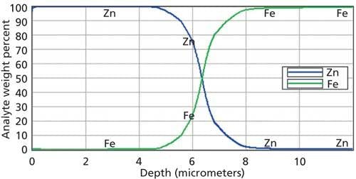
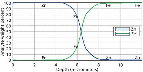
Figure 1: Zinc on steel.
Zn â 100% and Fe â 0%. As sputtering continues through the galvanized coating and into the steel substrate, the concentration of Zn decreases and the concentration of Fe increases. Both matrices must be calibrated so that the working curves span from traces to 100%. Additional elements should be calibrated to cover the range expected in either matrix.
Factory calibrations are possible for a wide range of materials including:
• Galvanizingâhot dipped, electrogalvanized,
• Galvannealed, Zn-Ni, Zn-Al, and so on,
• Aluminizing
• Aluminum clad
• ElectroplatingâAu, Cu, Ni, Cr, and so on,
• Tinplate
• PVD and CVD
• Heat treatmentsâcarburized, nitrided, carbonitrided, nitrocarburized
• Thin oxide layers
• Painted metal
To read the application note in its entirety, go to www.leco.com/library-search and reference 209-076-041.
LECO Corporation
3000 Lakeview Avenue, St. Joseph, MI 49085
tel. (800) 292-6141, (269) 985-5496
Website: www.leco.com