Small-Angle X-ray Scattering from Lamellar Structures
Lamellar structures are common in many polymeric materials and biological tissues. These structures are characterized by alternating layers of different compositions or densities that act as electron density gratings that diffract X-rays, giving rise to reflections at small scattering angles. This paper discusses the characteristics of these small-angle X-ray scattering patterns, relate these parameters to the features of the lamellar structure, and describe the analyses of these features to investigate deformations at the microstructural length scales. Structural models generated using known principles of lamellar assembly and evolution can be refined by comparing the simulated and the observed diffraction patterns. The method is illustrated using data from semicrystalline polymers where the contrast arises from the electron density differences between the crystalline lamellae and the amorphous segments. Use of these data to study the deformation of lamellae under strain is presented.
The fundamental structural unit in many crystallizable polymers is the lamella, consisting of tightly packed polymer chains. Lamellar structures also occur in block copolymers, in amphiphilic molecules such as surfactants and lipids, and in the smectic and discotic phases of liquid crystals. Lamellae also occur in biological structures—for example, lipids are packed as a liquid crystalline bilayer in cell membranes, on skin, and in the myelin sheath around nerve fibers, and collagen fibrils are organized into lamellar stacks in the cornea. This article discusses the basic characteristics of lamellar structures, and describes how disorders in these structures manifest in small-angle X-ray scattering (SAXS) patterns. We use the data obtained during deformation to illustrate the use of SAXS patterns.
Lamellar phases are 3D layered structures. The scattering pattern in the lamellar stacks arises from the differences in electron density between the lamellae and the interlamellar segments. Lamellar structures have 1D quasi-long-range order normal to the surface of the lamellae; because of this reduced dimensionality, they have unique physical properties and challenging theoretical descriptions. The methods used to investigate lamellar structures are quite different from those used for studying the more common 3D structures, and the more recent 2D structures, such as graphene and ultrathin layers of transition metal chalcogenides and MXenes (1,2).
Characteristics of the SAXS Patterns from Lamellar Structures Lamellae arranged in a stack form a diffraction grating. In oriented materials that are discussed here, the stacks are preferentially oriented (lamellae normal along the z-axis in Figure 1), giving rise to a diffraction pattern that typically consists two spots symmetrically arranged along z (Figure 1a). The position of the spot from the beam center, defined by the scattering angle 2θ or the scattering vector q (4π sinθ/λ), is related to the spacing Lz between the sheets by Bragg’s law, λ = 2Lz sinθ or Lz = 2π/q.
Figure 1 shows the different classes of SAXS patterns that are typically observed for oriented specimens. The patterns have been shown to arise from different combinations of rotations and displacement of the layers and stacks (3,4). The two-point pattern arises from lamellae whose surface is perpendicular to the orientation direction (Figure 1a). The limited lateral size of the lamellar stack spreads the reflections along a layer line; imperfect orientation adds some rotation, giving the appearance of a banana pattern. If the layers rotate about their lattice point, like the slats in a venetian blind, then the reflections can spread even more along a layer line if the rotation is continuous. A four-point pattern results when this rotation angle has a preferred value (Figure 1b–1d). The angle that the lamellae normal makes with the orientation direction (z) and tilt angle, ф, determines the azimuthal separation of the reflection in the four-point pattern (Figure 1b). In addition to the tilt of the lamellae, the stack can also rotate (rotation angle α). Depending on the sense of ф and α, either eyebrow (Figure 1c; ф and α in the same direction) or butterfly (Figure 1d; ф and α in opposite directions) patterns are produced.

 two-point banana pattern; (b) four-point pattern; (c) four-point eyebrow; (d) four-point butterfly.")
FIGURE 1: Four classes of SAS patterns and corresponding lamellar arrangements. Overlaid are the proposed elliptical tracks. (a) two-point banana pattern; (b) four-point pattern; (c) four-point eyebrow; (d) four-point butterfly.
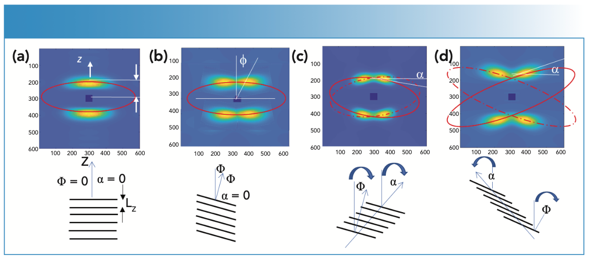
Three parameters, Lz from the position of the spots along 2θ, ф from the position of the spot along the azimuth, α from the tilt of the reflection from the layer line, can characterize the essential features of SAXS patterns. Additional parameters are required to fully account of the diffuse nature of the reflections. The spread or the width of the reflection in the radial (2θ) and the azimuthal (χ) directions may correspond the height (h) and the width (w), respectively, of the lamellar stacks.
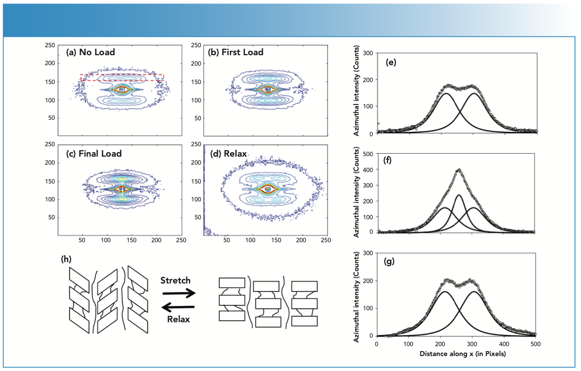
The apparent stack rotation, which splits the lamellar reflection, would move the reflections along a circular arc (5,6). But the trajectory of the reflection in all instances (Figures 2b–d) is not a circular arc. Neither is it a line perpendicular to z, which could be because of either the spread the reflections along a layer line because of limited stack width, or to the rotation around the center of mass of each lamella at a constant Lz. Instead, these reflections move along an elliptical trajectory (6,7). Such elliptical trajectory is predicted by the affine deformation of the lattice, which forms the basis for the lamellar stack. It is possible to obtain an elliptical trajectory by a combination of a range of whole-body, uncorrelated rotations of the stacks, and layer line spread (8). Although one ellipse may be sufficient for two-point patterns, two ellipses are required to describe the four-point pattern, one for each pair of reflections as shown in Figures 1c and 1d; this is further discussed later. Changes in the ellipticity are related to changes in the arrangement of the lamellae. Elliptical features are also common in mesostructured silica (9), laponite clay gels (10), block copolymers (11), and in diffuse scattering from oriented polymer chains (12–14).

–(d) Changes in the diffraction pattern: (a)–(b) during uniaxial deformation. (e)–(g) traces through the lamellar reflections parallel to the equator. (h) Bi-stable lamellar structure showing that the lamellae can flip between two structures, depending on whether it is relaxed or under strain.")
FIGURE 2: (a)–(d) Changes in the diffraction pattern: (a)–(b) during uniaxial deformation. (e)–(g) traces through the lamellar reflections parallel to the equator. (h) Bi-stable lamellar structure showing that the lamellae can flip between two structures, depending on whether it is relaxed or under strain.
Composite Patterns During Deformation
The patterns are not always simple two- or four-point patterns as indicated in Figure 1. Different patterns may coexist when the polymer undergoes melting or as it becomes deformed (15). Figure 2 shows the changes observed during deformation of nylon fibers (16). In this experiment, the drawn fiber has the four-point pattern. As the fiber is strained by external load, the four-point pattern progressively changes to a two-point pattern (Figures 2a–2d). At various stages during mechanical loading, the four-point and the two-point pattern coexist. This can be clearly seen in the horizontal 1D traces through the lamellar peaks (Figures 2e and 2f). When the load is released, the two-point pattern reverts back to the four-point patterns (Figures 2d and 2g). The two-point pattern arises from the untilted, metastable state of the lamellae. The four-point pattern arises from tilted lamellae, which are the stable structures in relaxed polymers. Under strain, the lamellae flip, not gradually but suddenly, to the untilted state, giving rise to the two-point pattern (Figure 2h). Upon removing the load, the untitled lamellae flip back to the relaxed tilted state. Similar observations have been made in polyethylene terephthalate (PET) fibers (17,18). It was observed that, during cold drawing, the 2-D SAXS pattern transformed from a four-point pattern to the coexistence of two- and four-point patterns. The disappearance of lamellar peaks in final stages of drawing indicated the destruction of periodic lamellar structures caused by the surface fragmentation of crystalline layers (18).
SAXS Patterns and Mechanics of Deformation
The example discussed above reveals that detailed study of the SAXS pattern during polymer deformation, or in general during any structural changes (including melting), relates to changes at the lamellar length scale, and thus can be useful in understanding the linkages between the crystalline and amorphous chain segments. Accordingly, the influence of micromechanical deformations on the bulk mechanical properties of the material can be understood. Important elements of lamellar deformation are chain slip that causes lamellar tilt (ф), and slippage of the lamellae past each other, or interlamellar shear that results in stack rotation (α) without full body rotation (3,4). The two subclasses of the four-point pattern, the eyebrow and butterfly pattern, can be explained by invoking chain and lamellar slip; the first will cause lamellar tilt that will move the reflections off the z-axis, and the second will cause stack rotation that will rotate the reflections. If the tilt and the rotation are in the same direction, the result is the eyebrow pattern (Figure 3c), and if they are in the opposite direction, then it is the butterfly pattern (Figure 3d) (19).

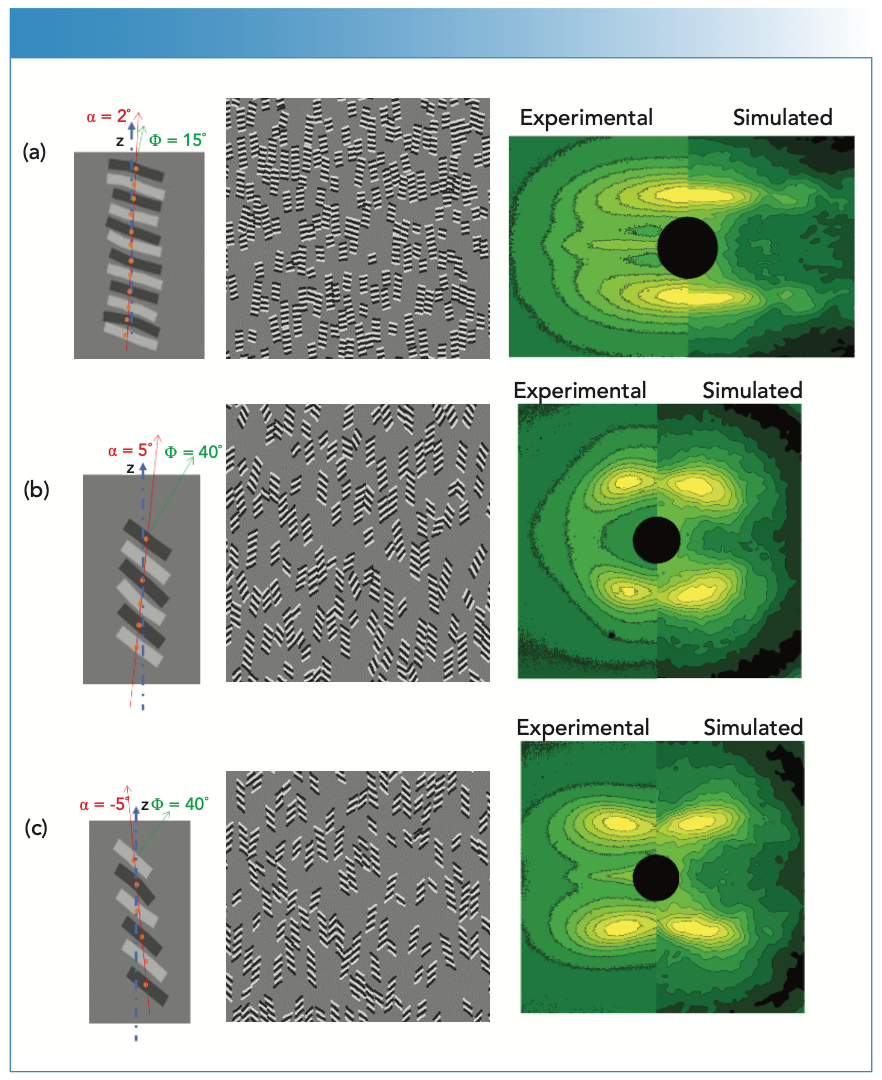
![FIGURE 3: Simulation of SAXS patterns by Fourier transform of model structures. The first column shows the organization of the lamellae within a stack. In these figures, φ is the lamellar shear angle or the stack rotational angle, and α is the lamellar tilt angle. These were varied to generate the three classes of diffraction patterns. The second column shows the space-filled structures used to generate the diffraction patterns. The third column com- pares the observed diffraction pattern (left half) with the simulated pattern (right half). The simulated patterns are from poly(ethylene-co-octene) polymers [21]. (a) Two-Point pattern: 38 wt% octene 300% strain. (b) Four-Point eyebrow pattern: 38 wt% octene, 600% strain and relaxed. (c) Four-Point butterfly pattern: 19 wt% octrene, 500% strain relaxed.](/_next/image?url=https%3A%2F%2Fcdn.sanity.io%2Fimages%2F0vv8moc6%2Fspectroscopy%2Fed3b6b88cb9e3ea52032aecd1427f1f7403dd453-882x1080.png%3Ffit%3Dcrop%26auto%3Dformat&w=1920&q=75 "FIGURE 3: Simulation of SAXS patterns by Fourier transform of model structures. The first column shows the organization of the lamellae within a stack. In these figures, φ is the lamellar shear angle or the stack rotational angle, and α is the lamellar tilt angle. These were varied to generate the three classes of diffraction patterns. The second column shows the space-filled structures used to generate the diffraction patterns. The third column com- pares the observed diffraction pattern (left half) with the simulated pattern (right half). The simulated patterns are from poly(ethylene-co-octene) polymers [21]. (a) Two-Point pattern: 38 wt% octene 300% strain. (b) Four-Point eyebrow pattern: 38 wt% octene, 600% strain and relaxed. (c) Four-Point butterfly pattern: 19 wt% octrene, 500% strain relaxed.")
FIGURE 3: Simulation of SAXS patterns by Fourier transform of model structures. The first column shows the organization of the lamellae within a stack. In these figures, φ is the lamellar shear angle or the stack rotational angle, and α is the lamellar tilt angle. These were varied to generate the three classes of diffraction patterns. The second column shows the space-filled structures used to generate the diffraction patterns. The third column com- pares the observed diffraction pattern (left half) with the simulated pattern (right half). The simulated patterns are from poly(ethylene-co-octene) polymers [21]. (a) Two-Point pattern: 38 wt% octene 300% strain. (b) Four-Point eyebrow pattern: 38 wt% octene, 600% strain and relaxed. (c) Four-Point butterfly pattern: 19 wt% octrene, 500% strain relaxed.
Both chain slip and lamellar shear act on opposing faces of the amorphous layer, and bring about net shear in the interlamellar amorphous layer (net shear angle Ψ = ф-α). When ф and α have the same sense, the amorphous segments deform less. Thus, the eyebrow pattern that occurs under these conditions signifies smaller amorphous deformation. Conversely, when ф and α have the opposite sense, the amorphous segments deform more. Thus, the butterfly pattern that occurs under these conditions signify larger deformation in the amorphous phase. If the stack rotation occurs without an interlamellar shear (for example, by stack rotation), then the shear is at both the stem and the fold surfaces of the lamellae. We find that, in low octene content polymer where strain hardening is observed, a butterfly pattern emerges when the load is removed, indicating large interlamellar shear. In high octene content polymers, where little strain hardening is observed, less interlamellar shear might explain the observed eyebrow patterns in the relaxed samples.
Modelling the Lamellar Structures
The parameters that describe the SAXS lamellar patterns, Lz, ф, α, h, and w, can be determined by profile fitting the reflections. This may be done as a sequence of 1D scans obtained by stepping across the pattern (20), or by fitting the entire 2D pattern in a single analysis. Because the reflections fall on an ellipse, such 2D profile fitting can be efficiently done in elliptical coordinates (7). Parameters of appropriately chosen functions can be used to determine the structure characteristics, such as lamellar spacing. However, functional analysis may not reveal new or unknown features present in the structure because it essentially parameterizes the patterns according to the features identified by the chosen functions. Modeling addresses this drawback, and provides an alternative to functional analysis. If a reasonable model for the structure can be assumed, then the simulated pattern compared with the observed pattern to iteratively refined to the observed pattern to arrive at the most plausible structure (Figure 3).
In one recent attempt, structural representations of the lamellar assembly were generated using Mathematica (9). In building this model, the lamellar stacks are rep- resented by parallelograms representing tilted and sheared lamellae. Assembly of many hundreds of non-overlapping parallelograms were used to represent the bulk structure. The shape of the parallelogram is defined by ф, and its tilt by α. To mimic the disorder in the system, the height, width, shear and tilt angles (h, w, ф, and α) for each lamellar stack were selected at random from normal distributions with preselected means and standard deviation. Once the space is filled with lamellar stacks, individual lamellae are inserted within each stack. Each is filled with two to six lamellae, represented by dark and white bands corresponding to the electron densities of the crystalline and amorphous layers. The lamellar spacing (Lz), stack length (h), stack width (w), the tilt angle (ф) because of chain slip and the stack rotation angle due to lamellar shear (α) were varied. Additionally, “waviness” was introduced to mimic the stack disorder, and reproduce the breadth of the reflections in the observed patterns. The square of the amplitude of the 2D Fourier transform of the generated test objects represents the diffraction pattern.
Figure 3 shows the basic lamellar stack, assembly of lamellar stacks, and a comparison of the simulated and the observed diffraction patterns. Three representative models of the lamellar stacks corresponding to three distinctive classes dis- cussed earlier were used (Figure 1). The observed patterns shown on the left half of the figure in column 3 were obtained by Stribeck and coworkers from poly(ethylene-co-1-octene)s (21). There is a remarkable degree of agreement between the observed and calculated diffraction patterns showing that simulations can give insight into the structures that give rise to the diffraction patterns. However, it is necessary to realize that such lamellar models are only one possible solution, not necessarily the correct one. Other independent evidence is required to validate the structural models. These validated models will be useful to understand the micromechanical deformation of the lamellar stacks by following the lamellar parameters discussed earlier. With the current computing power, these tools can be used to derive possible morphologies of materials as they are being deformed under mechanical load in real time at X-ray sources.
Conclusions
2D SAXS pattern provide a rapid and rigorous means for quantifying the dynamic changes in the lamellar structures during transformation such as during strain or melting. The features that are important to quantify are L, ф, α, h, and w, and the spread in these parameters. These parameters can be determined by 2D functional analysis of the pattern. Alternatively, details of the structure that gives rise to the various features of the SAXS pat- terns can be built into a structural model, and validated by comparing the simulated pattern with the observed pattern.
References
(1) A. VahidMohammadi, J. Rosen, and Y. Gogotsi, Science 372(6547) (2021).
(2) E. Lhuillier, S. Pedetti, S. Ithurria, B. Nadal, H. Heuclin, B. Dubertret, Acc. Chem. Res. 48(1), 22–30 (2015).
(3) G.W. Groves and P.B. Hirsch, J. Mater. Sci. 4(10), 929–932 (1969).
(4) D.P. Pope and A. Keller, J. Polym. Sci. 13(3), 533–566 (1975).
(5) H.H. Song, A.S. Argon, and R.E. Cohen, Macromolecules 23(3), 870–876 (1990).
(6) N.S. Murthy, D.T. Grubb, and K. Zero, Macromolecules 33, 1012–1021 (2000).
(7) N.S. Murthy, K. Zero, and D.T. Grubb, Polymer 38, 1021–1028 (1997).
(8) D. Grubb, N.S. Murthy, and O. Francescangeli, J. Polym. Sci., Part B: Polym. Phys. 54(2), 308–318 (2016).
(9) R.C. Hayward, P.C.A. Alberius, E.J. Kramer, and B.F. Chmelka, Langmuir 20(14), 5998–6004 (2004).
(10) B.J. Lemaire, P. Panine, J.C.P. Gabriel, and P. Davidson, EPL 59(1), 55 (2002).
(11) M. Brandt and W. Ruland, Acta Polymer 47, 498–506 (1996).
(12) K. Hahn, J. Kerth, R. Zolk, D. Schwahn, T. Springer, and J. Kugler, Macromolecules 21(5), 1541–1543 (1988).
(13) G. Hadziioannou, L.H. Wang, R.S. Stein, and R.S. Porter, Macromolecules 15(3), 880–882 (1982).
(14) P. Young, R.S. Stein, T. Kyu, and J.S. Lin, J. Polym. Sci., Part B: Polym. Phys. 28(10), 1791–1812 (1990).
(15) H. Koerner, J.J. Kelley, and R.A. Vaia, Macromolecules 41(13), 4709–4716 (2008).
(16) N.S. Murthy and D.T. Grubb, J. Polym. Sci., Part B: Polym. Phys. 40, 691–705 (2002).
(17) N.S. Murthy, and D.T. Grubb, J. Polym. Sci., Part B: Polym. Phys. 41, 1538–1553 (2003).
(18) Y. Liu, L. Yin, H. Zhao, G. Song, F. Tang, L. Wang, H. Shao, and Y. Zhang, Polymer 119, 185–194 (2017).
(19) D.T. Grubb, W.J. Kennedy, H. Koerner, and N.S. Murthy, Polymer 220, 123566 (2021).
(20) N.S. Murthy, C. Bednarczyk, R.A.F. Moore, and D.T. Grubb, J. Polym. Sci., Part B: Polym. Phys. 34, 821–835 (1996).
(21) R. Androsch, N. Stribeck, T. Lüpke, and S.S. Funari, J. Polym. Sci., Part B: Polym. Phys. 40(17), 1919–1930 (2002).
N. Sanjeeva Murthy is with the Department of Chemistry and Chemical Biology at Rutgers University, in Piscataway, New Jersey. W. Joshua Kennedy and Hilmar Koerner are with the Materials and Manufacturing Directorate at the Air Force Research Laboratory of the Wright-Patterson Air Force Base, in Dayton, Ohio. David Grubb is with the Department of Materials Science and Engineering, at Cornell University, in Ithaca, New York. Direct correspondence to: nsmurthy@chem.rutgers.edu ●


 in Philadelphia. The university exists since 1740 and had 21,599 students in 2018. | Image Credit: © Tupungato - stock.adobe.com")
University of Pennsylvania Graduate Researcher Wins SPIE Medical Imaging Student Paper Award
March 14th 2024A PhD student in the Department of Bioengineering at the University of Pennsylvania has won the 2024 Physics of Medical Imaging Student Paper Award, which is given out annually by the International Society for Optics and Photonics (SPIE), at the Medical Imaging Symposium in San Diego, California.


Advancements in Non-Invasive Analysis of Historical Metal Artifacts
December 19th 2023Studying historical ancient artifacts requires the use of a nondestructive technique to analyze the metal surfaces of these objects. This study presents two approaches that improves on existing methods when conducting alloy analysis.

Unraveling Polyester Fibers with Advanced X-Ray Techniques
December 5th 2023Researchers at Kochi University and RIKEN have unveiled a new method for distinguishing individual polyester fibers in forensic investigations. Published in Spectrochimica Acta Part B: Atomic Spectroscopy, their advanced X-ray analysis refreshes how we unravel the composition of these fibers.

