|Articles|February 1, 2008
- Spectroscopy-02-01-2008
- Volume 23
- Issue 2
Miniature Optical Spectrometers: Follow the Money Part II: The Telecommunications Boom
Author(s)Richard A. Crocombe
The author examines NIR spectrometers and the technologies developed during the telecommunications boom of the late 1990s, focusing on miniaturized optical techniques generally called MOEMS.
Advertisement
In Part I of this series (2), we saw that there are straightforward motivations for miniaturizing an optical spectrometer. If an instrument can be made smaller, it will often also consume less power, enabling it to be portable and eventually handheld. This allows the spectrometer to be taken to the sample, as opposed to taking the sample to the spectrometer, and this typically leads to increased productivity in traditional applications. Small size often also implies lower cost, and this opens up nontraditional applications. In addition, the recently developed technologies that enable miniature spectrometers can be regarded as disruptive, and instruments based upon those technologies find niches at the low-price end of the market, in new applications, where their performance is "good enough." However, because the performance of these newer products typically progresses faster than their mature counterparts, they rapidly become competitive with these mature products and eventually meet the performance requirements of the majority of the market. This scenario can lead to the demise of the previously dominant products and technologies.
Part I of this series addressed the mid-infrared (MIR) region, where Fourier-transform (FT) spectrometers dominate the scene, and small versions of laboratory instruments have been developed (2). However, several other technologies are being implemented for niche applications in the MIR, including slab-waveguide spectrometers, lower cost array detectors, linear variable filters, tunable lasers, and photonic crystals (2). A number of FT-IR spectrometers using micro electro mechanical systems (MEMS) technologies also have been developed (2). The performance of spectrometers is highly dependent on their optical throughput, especially in the MIR, where sources are less bright and detectors are poorer, as compared with the NIR region. A miniature spectrometer implies low throughput, and this potentially compromises the applications of miniature instruments.
In this article, we will examine the technologies developed during the telecommunications boom of the late 1990s, focusing on miniaturized optical techniques generally called micro-opto-electro-mechanical systems (MOEMS) (3). Some of these technologies only began to be applied to spectroscopy a few years ago, and we have yet to see their full impact. Part III of this series will survey conventional small NIR spectrometers, and Part IV will describe new miniature NIR spectrometers based upon MOEMS and telecommunications photonic technologies.
The Telecommunications Boom
In the late 1990s, a vision of an annual telecommunications equipment market of $110 billion caused around $20 billion to be invested in optical communications companies, spawning a multitude of developments (4). These devices are all described in standard texts on photonics (5), and include pump laser diode modules, semiconductor tunable lasers (6), optical gain media and fiber amplifiers, optical fibers, optical switches, detectors, gratings, fiber Bragg grating sensors, photonic crystals, and tunable filters. The size of many of these components is particularly interesting, because fiber optics used in communications today have a core diameter of ~8 μm and operate in single mode. The small size of these single-mode fibers in turn mandates that all the other optical components be on that scale; therefore, a huge industry grew up that involves devising and manufacturing miniature optical components. Furthermore, telecommunications applications require that devices be incredibly reliable and rugged and operate under a wide range of temperature, vibration, and humidity conditions; those properties make them very attractive for many applications outside telecommunications. The massive amount of investment in this market also spurred intense competition, resulting in very low prices for these components, especially after the dot-com and telecomm bubbles burst about five years ago. After that market crash (4), there was interest in applying these technologies in other applications. Even after the market crash and resulting business consolidation, developments in optical communications and communications technology continue, and the long-awaited deployment of fiber-to-the-home (FTTH), now with an installed base of 2 million subscribers in the US (7), and increasing bandwidth demand from downloadable music and video, are spurring new investment.
Because of the nature of optical communications, most of these telecomm devices work in the NIR region. These developments are now fueling a new generation of small NIR spectrometers; to understand those developments and anticipate the next generation of instruments, we need to follow Deep Throat's advice to Bob Woodward (8) and "follow the money" — follow all the developments in telecommunications, photonics, and MOEMS, funded by those billions of dollars of investment.
MEMS, MOEMS, and Telecommunications
MEMS processing technologies were developed during the 1980s in response to a demand for rugged, miniature sensors, and during the 1990s micro-optics technology was developed (9), both in industry and at national laboratories; Motamedi has given a historical outline (10). Key applications were optical switches for telecommunications, components for wavelength division multiplexing (WDM), digital mirror devices (DMDs), and optical scanners. MOEMS and optical communications have their own terminologies, abbreviations, and acronyms, and we will describe a few of them here. MEMS techniques are widely used in nonspectroscopic areas of analytical chemistry, principally in microfluidics, but those applications (11) will not be covered here.
A microprocessor chip has all-electrical connections and no internal moving parts. A MEMS chip has, by definition, moving parts, and a MOEMS chip adds an optical interface as well. Given that very small contaminants can cause a chip function to fail, packaging (12,13) — the placement of the chip in a dry, clean, hermetically sealed, but interconnected, environment — is a critical issue. Telecommunications MOEMS devices typically employ optical fibers and fiber feed-throughs in and out of device packages, so that many devices (such as pump lasers and filters) are referred to as fiber-pigtailed, while MEMS display devices require optical windows in the package. Devices and other materials in a package tend to outgas, and this can cause performance problems; therefore, getters (reactive materials used to remove traces of gas) are included within the packages. Packaging is not widely described in the literature; instead, it is frequently regarded as a proprietary technology, but interested readers can refer to references 12 and 13.
In process control terminology, an actuator is a powered mechanism that causes motion of a part. The motion of many MOEMS devices is enabled by a comb drive actuator, silicon-based linear motors, which operate using electrostatic forces. Figure 1 shows a comb drive developed by Sandia National Laboratories (Albuquerque, New Mexico), and the interdigitating teeth in the combs can be seen clearly; the teeth are designed so that they can slide past each other. A potential difference between the two combs causes electrostatic attraction between them. The magnitude of this force depends upon the voltage difference, the number of comb teeth, and the length of the teeth; the force decreases when the combs are further apart.
Figure 1
A large class of MOEMS devices are optical scanners (14), which can control the position of an optical light beam; these find a multitude of applications in imaging, barcode scanners, and printing. Optical scanners use movable mirrors that move around one or two axes: motion of a mirror, or an array of mirrors, can manipulate light by reflection or by diffraction. Replacing the mirror in an optical scanner with a MEMS grating leads to a miniature scanning grating device, which clearly has spectroscopic applications. Very complex MEMS and MOEMS devices have been fabricated using Sandia National Laboratories' SUMMiT V process (15): a five-layer polycrystalline silicon surface micromachining process, with one ground plane–electrical interconnect layer and four mechanical layers. In spectroscopy, this process is being used for the Block Engineering (Marlborough, Massachusetts) MEMS FT-IR program (16). As examples of Sandia's MOEMS technology, Figure 2 shows a gear reduction system, and Figure 3 shows a mechanism that erects a silicon mirror.
Figure 2
Optical Fiber Communications Technologies
Saleh and Teich (17) give a condensed history of the evolution of optical fiber communication systems. At a very basic level, efficient optical communication requires powerful light sources (LEDs and lasers) that can be modulated rapidly, and then fast-response detectors for the light wavelengths employed. In the 1970s, the first systems operated around 870 nm, using AlGaAs LEDs and laser diodes, with silicon positive-intrinsic-negative (PIN) diode and avalanche photodiode (APD), detectors. However, at longer wavelengths, both fiber attenuation (that is, absorption) and dispersion (18,19) (change of refractive index with wavelength) in silica fibers are smaller, and the next systems were designed for 1310 nm operation ("O-band"), which is the point of minimum dispersion. Dispersion causes light at different wavelengths to travel at different speeds in the fiber; this broadens pulses of light, and ultimately limits the information transmission rate. These O-band systems used InGaAsP lasers with InGaAs PIN or APD detectors. Silica fibers have their lowest attenuation (but nonzero dispersion) around 1550 nm ("C- and L-bands"). The dispersion issue was addressed using graded index optical fibers, distributed feedback (DFB) lasers, based upon InGaAsP, and again InGaAs detectors were used. Over distance, optical communication signals require periodic amplification, and this has been done with semiconductor optical amplifiers (SOAs) and optical fiber amplifiers (OFAs), the most common of which is the erbium doped fiber amplifier (EDFA). Today, many telecomm lasers are vertical-cavity surface-emitting lasers (VCSELs) (20), which are multi-quantum well devices, based upon GaAs–InGaAs, and light is emitted from their top face. They can be fabricated in the form of arrays, with individual elements emitting at different frequencies.
Figure 3
To carry more information down a single optical fiber, many channels, operating at different optical frequencies in the "C-band" (1530–1565 nm) and "L-band" (1565–1625 nm) regions, are used (21,22). This is termed wavelength division multiplexing (WDM), and dense wavelength division multiplexing (DWDM). DWDM systems use channel spacing as small as 50 GHz, which, in more familiar spectroscopic units, is 1.66 cm–1 (everywhere in the spectrum, because they are both frequency units), and at 1550 nm this corresponds to ~0.4 nm. Clearly, means are required to separate and detect a large number of closely spaced wavelengths, requiring the development of miniature high-resolution wavelength-selective devices: gratings, variable filters, interferometers, and rapidly-tunable filters, as well as linear detector arrays.
Miniature lenses are also required, and one means of accomplishing this is the use of graded index materials: GRIN lenses. In these devices, the refractive index of the material is varied gradually to bring light to a focus. These lenses are manufactured with a small cylindrical form factor, with a radial index gradient, and are self-aligning. They are often referred to under their trade name of SELFOC lenses (NSG America, Inc., Somerset, New Jersey) (23). A typical diameter is 1–2 mm, and length is a few millimeters. Miniature lenses and lens arrays have been fabricated by a number of other techniques (9,24,25), and one interesting method for materials such as GaP and InP is mass transport. In this technique, a lens preform with the desired profile expressed digitally at low resolution is etched in the material and is subsequently annealed; the material has a finite vapor pressure at elevated temperatures and redistributes to form a smooth profile. Figure 4 shows a mass transport lens preform, and Figure 5 a finished array of GaP lenses.
Figure 4
WDM and DWDM require an optical multiplexer to mix the signals together and a demultiplexer to separate them (5), as well as devices to measure the power in each channel — optical power monitors (OPMs) or optical channel monitors (OCMs) — and subsequently rebalance those powers, using a variable optical attenuator (VOA). A number of MOEMS devices have been developed for use as VOAs to control optical power in networks, cross-connects, and add–drop multiplexers. We shall see in Part IV of this series how Axsun Technologies' (Billerica, Massachusetts) NIR spectroscopy products evolved from their OCM business. Finally, there is a need to switch optical network traffic remotely, without converting optical signals back to electrical signals: the key MOEMS component is called an optical cross-connect, which has the ability to switch N input channels to N output channels, in any configuration (26). The complete devices are called reconfigurable optical add–drop multiplexers (ROADMs) (27), and a number of different optical devices have been developed for this application, including 'active gratings.' One device of this type is now the key component in Polychromix's (Wilmington, Massachusetts) handheld NIR spectrometer (see Part IV).
Figure 5
The LIGA Technique
LIGA (28–31) is a German acronym for X-ray lithography (lithographie), electroplating (galvanoformung), and molding (abformung), and was developed at the Forschungszentrum Karlsruhe (Germany) in the early 1980s (32). An X-ray mask defining the desired part is placed over a photoresist, such as polymethylmethacrylate (PMMA), and the combined part is exposed on a synchrotron beamline, which produces an intense, highly parallel beam of X-rays (Figure 6). A well-defined hole is produced in the photoresist, with smooth, vertical sides; the roughness of the sidewalls can be less than 20 nm. The dimensions of details in the x–y direction can be as small as 200 nm, while a typical depth (z-direction) of the hole is 150 μm to 1 mm. The resultant devices, therefore, can have a high aspect ratio: the ratio of the width of details in the structure to its depth. The hole is then filled in via a metal electroplating step, typically with nickel; the PMMA is then dissolved and the part freed. In practice, of course, hundreds or thousands of parts are made simultaneously. Some examples of Axsun Technologies' LIGA optical mounts are shown in Figure 7. The photoresist holes can be overfilled during the plating process, in which case the resulting metal part can be used as a master for precision embossing or injection-molding processes, and then final parts can be made of a plastic material. Multilevel structures also can be created using LIGA, by bonding a second layer of PMMA to the first, after the electroplating process is complete.
Figure 6
Digital Light Projectors
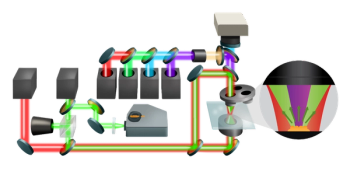
Texas Instruments' (Dallas, Texas) Digital Light Projector (DLP) is probably the most common MOEMS device, with 10 million units in computer-based projectors (Figure 8) shipped by 2006, after its commercial introduction in 1996 (33). The underlying technology, a digital mirror device (DMD), was invented in 1987. The design and packaging of the DLP chip are described in detail elsewhere (34,35), but a few details will be given here, because, as we shall see, the DLP chip can be used as the key component in a Hadamard transform spectrometer. The DLP chip consists of an array of mirrors that can be driven ±10° from a rest position, and these angles are determined by position stops or "landing sites," so they are very precise (Figure 9). One position is "on" and light will reach the screen, and the other is "off" and light is directed into a trap. The mirrors are aluminum-coated silicon, and are 16-μm square on 17-μm centers, leading to a fill factor of over 90%. The fill factor is high because all the hinge mechanisms are below the mirror itself. Each mirror is capable of switching on and off up to several thousand times per second. When a mirror is switched on more frequently than off, it reflects a light pixel; a mirror that is switched off more frequently reflects a darker pixel. The available resolution (number of pixels) in these devices has increased steadily over the past ten years. An office projector today is often SXGA or 1280 × 1024 resolution (1,310,720 pixels), and cinema projectors are 2048 × 1080 resolution.
Figure 7
The DMD array chip is attached to an alumina substrate, which is brazed to a Kovar ring. The optical window is attached to a Kovar frame with a fused seal, and finally the window frame is welded to the seal ring, creating a hermetic package. There are also getter strips inside the package. Texas Instruments now offers the DLP chip with a choice of three windows: Standard visible, IR, and UV. The IR window transmits to about 2500 nm, has greater than 90% transmission from 900–2100 nm, and has less than 50% transmission at shorter than 500 nm (36).
Figure 8
Fabry-Pérot Interferometers
Although many different wavelength separation techniques have been used in optical communications, the dominant one is the use of Fabry-Pérot interferometers (37), devices that found few widespread commercial applications for almost 100 years (38). A Fabry-Pérot filter consists of two mirrors, either plane or curved, facing each other and separated by a distance d. There are two basic versions: an interferometer, where d is variable, and an etalon, where d is fixed. The condition for constructive interference within a Fabry-Pérot interferometer is that the light forms a standing wave between the two mirrors, in which case the optical distance between the two mirrors must equal an integral number of half wavelengths of the incident light. When a Fabry-Pérot cavity is on resonance, constructive interference within the cavity allows transmission of essentially 100% of the light through the filter. When the cavity is off resonance, the Fabry-Pérot filter reflects nearly all the incident light.
Figure 9
These interference effects are most familiar to MIR spectroscopists because of the fringes, or channel spectra, frequently observed when using transmission cells, measuring spectra of thin polymer films, or silicon wafers (39). These are samples with low-reflectivity, plane parallel surfaces (such as etalons), and the resulting fringes resemble a cosine wave in the spectrum. These fringes can be used for thickness measurement, and dedicated interferometric instruments have been used for many years in the semiconductor business for exactly this purpose (40).
Figure 10
The difficulty of fabricating a Fabry-Pérot with highly reflecting parallel faces and a small spacing, along with its limited free spectral range, has meant that this technique has not been used for analytical spectroscopy and has been limited to a few specialist high-resolution applications. However, it is worth noting that a Fabry-Pérot interferometer, with a circular aperture, does have a throughput advantage over a grating, similar to a Michelson interferometer. This was realized by Jacquinot in his early work on high-resolution spectroscopy (41).
Because of the widespread use of Fabry-Pérot interferometers in telecommunications and their increasing use in a number of innovative miniature spectrometers (Part IV), we will cover the theory of the Fabry-Pérot here, and contrast it with the more familiar Michelson interferometer.
In the Fabry-Pérot interferometer, for normal incidence and an air gap, we have the following relationships:
d = mλ/2 or λ=2d/m
where d = mirror separation
m = an integer
λ = wavelength of light resonant in the interferometer
Therefore, changing the mirror separation (d) tunes the transmitted wavelength (λ) of a Fabry-Pérot interferometer.
Transmission through a Fabry-Pérot filter is periodic with wavelength, and the distance between two wavelength transmission orders is the filter free spectral range (FSR):
FSR = λ2 /2d
Alternatively, this can be stated as the frequency spacing between modes:
FSR = c/2d
Note that the FSR is a constant in frequency space, but not in wavelength space (Figure 11).
Figure 11
The spectral resolution, defined as the full-width-half-maximum (fwhm) at the peak transmission, depends upon the finesse (F) of the Fabry-Pérot, which, in turn, is determined by the reflectivity (R) of the cavity mirrors.
F = (π√R)/(1-R)
Resolution = FSR/F
Therefore, if you can achieve a reflectivity of 99.9%, the finesse is greater than 3000, and for an FSR of 150 nm at 1500 nm, the resolution will be 0.5 nm, or about 2 cm–1. Note that increasing the cavity length, and therefore decreasing the FSR, improves the resolution; this effect is shown graphically in Figure 12.
Figure 12
A general formula for the transmission function (T) through the Fabry-Pérot is:
This shows that the lineshape is a Lorentzian function. Figure 13 shows the effect of small changes in cavity length on the transmission function. This is the usual scanning mode of a Fabry-Pérot interferometer; in a first-order approximation, the resolution and FSR are constant, and the lineshape function translates, scanning a spectrum.
Figure 13
Table I compares the critical attributes of Fabry-Pérot and Michelson interferometers.
Table I: The critical attributes of Fabry-Pérot and Michelson interferometers
It is therefore clear why the Fabry-Pérot has been attractive in telecommunications: high spectral resolution is required, but only over a narrow spectral range (60 nm at around 1550 nm), in a compact package, with minimal moving parts. Those specifications are a good match for a MOEMS Fabry-Pérot device.
Focalplane Arrays
Some focalplane arrays can be classified as MEMS or MOEMS devices; these are uncooled thermal imagers (42), employing microbolometer or microthermopile technologies. In a bolometer, light falls on a thermally isolated structure, causing a change in temperature and a change in electrical resistance, measured by an external circuit. In a design originally developed by Honeywell, a film of vanadium oxide on silicon nitride is the detecting material; in another design, amorphous silicon is the thermistor (34). The microbolometer pixel is formed into a microbridge, suspended above the substrate and connected via thin support legs. To minimize heat loss in the detector element, the array is vacuum packaged and the legs are made as long and narrow as feasible, using a low thermal conductivity material.
Foote and colleagues (43,44) have described a series of micromachined thermopile arrays (29). Thermopiles are made of dissimilar materials, in this case Bi-Te and Bi-Sb-Te, in which half of the junctions are exposed to the thermal radiation and the other half are shielded from it. The difference in temperatures between the two junctions gives rise to a voltage (an EMF). A thermopile has an almost constant response across the spectrum and does not require cooling; they operate without a chopper, have negligible 1/f noise, and do not require a bias. Therefore, they can be well suited to a portable spectrometer (2). A linear, 64-element thermopile array, based on bismuth-antimony thermocouples, also has been described in detail (45,46). This particular array uses a silicon nitride substrate, Bi0.87Sb0.13/Sb thermoelectric material, and "black" silver as the absorbing material, with an individual pixel having an area of 0.675 mm2 . It achieves a D* of 1.6 × 10⁹ cmHz1/2 /W.
In Part IV of this series we will describe novel NIR array detector-based spectrometers, and also innovative devices in which MEMS wavelength-selective elements are combined, on-chip, with array detectors.
Conclusions
As a result of the telecommunications boom (and bust!), a large number of miniature optical devices and actuators were developed. In this paper we "followed the money" to understand these MEMS and MOEMS fabrication processes and miniature optical components because they are starting to make an impact in analytical spectroscopy. Part IV of this series will describe new miniature NIR spectrometers based on these MOEMS and telecommunications photonic technologies, but first, Part III will survey conventional small NIR spectrometers.
Acknowledgments
The author thanks the following individuals and companies for permission to reproduce the Figures: Sandia National Laboratories, Axsun Technologies, and Texas Instruments. The author also wishes to thank Mark Kuznetsov (Axsun Technologies) for assistance with Figures 11–13.
Richard A. Crocombe is with ThermoFisher Scientific in Billerica, Massachusetts.
References
(1) C.M. Christenson, The Innovator's Dilemma: When New Technologies Cause Great Firms to Fail (Harvard Business School Press, Boston, 1997).
(2) R.A. Crocombe, Spectroscopy 23(1), 38–56 (2008).
(3) M.E. Motamedi, Ed., MOEMS: Micro-Opto-Electro-Mechanical Systems (SPIE Press, Bellingham, Washington, 2005).
(4) R.S. Payne, Proc SPIE-Int. Soc. Opt. Eng. 5717, 79–88 (2004).
(5) B.E.A. Saleh and M.C. Teich, Fundamentals of Photonics, 2nd ed. (Wiley-Interscience, Hoboken, New Jersey, 2007).
(6) M. Wippich and K. Li Dessau, The Industrial Physicist, 24–27 (June/July 2003).
(7) FTTH Market Report by RVA (
(8) William Goldman's script for "All The President's Men",
(9) J. Jahns and K.-H. Brenner, Eds., Microoptics: From Technology to Applications (Springer-Verlag, New York, 2004).
(10) M.E. Motamedi, Chapter 1 in MOEMS: Micro-Opto-Electro-Mechanical Systems, M.E. Motamedi, Ed. (SPIE Press, Bellingham, Washington, 2005).
(11) A.K. Deisingh, Analyst 128, 9–11 (2003).
(12) A.P. Malshe and J.P. O'Connor, Chapter 11 in MOEMS: Micro-Opto-Electro-Mechanical Systems, M.E. Motamedi, Ed. (SPIE Press, Bellingham, Washington, 2005).
(13) R. Frank, Small Times, 7(5), 8–12 (September/October 2007).
(14) T. Bourouina, H. Fujita, G. Reyne, and M.E. Motamedi, Chapter 7 in MOEMS: Micro-Opto-Electro-Mechanical Systems, M.E. Motamedi, Ed. (SPIE Press, Bellingham, Washington, 2005).
(15) Sandia National Laboratories SUMMiT V Web site:
(16) E.R. Schildkraut, D. Reyes, D.J. Cavicchio, and J.O. Jensen, "A MEMS Based Micro-Spectrometer For Toxic Vapor Detection And Identification," Presented at the Scientific Conference on Chemical and Biological Defense Research (2004) held in Hunt Valley, Maryland, on 15–17 November 2004. Available on Block Engineering Web site:
(17) B.E.A. Saleh and M.C. Teich, In Fundamentals of Photonics, 2nd ed. (Wiley-Interscience, Hoboken, New Jersey, 2007), Chapter 24.
(18) F.G. Smith and T.A. King, Optics and Photonics: An Introduction (John Wiley & Sons, Chichester, UK, 2000), pp. 345–352.
(19) E.F. Schubert, Light Emitting Diodes (Cambridge University Press, New York, 2003), Chapter 13.
(20) B.E.A. Saleh and M.C. Teich, In Fundamentals of Photonics, 2nd ed. (Wiley-Interscience, Hoboken, New Jersey 2007), Chapter 17.
(21) G. Sanger, The Industrial Physicist, 18–21 (February/March 2002).
(22) B.E.A. Saleh and M.C. Teich, Fundamentals of Photonics, 2nd ed. (Wiley-Interscience, Hoboken, New Jersey, 2007), Chapters 23 and 24.
(23) NSG America,
(24) H.P. Herzig, E.-B. Kley, M. Cumme, and L.C. Wittig, Chapter 3 in MOEMS: Micro-Opto-Electro-Mechanical Systems, M.E. Motamedi, Ed. (SPIE Press, Bellingham, Washington, 2005).
(25) M.E. Motamedi and J. Schwider, Chapter 5 in MOEMS: Micro-Opto-Electro-Mechanical Systems, M.E. Motamedi, Ed. (SPIE Press, Bellingham, Washington, 2005).
(26) R. Göring, Chapter 6 in MOEMS: Micro-Opto-Electro-Mechanical Systems, M.E. Motamedi, Ed. (SPIE Press, Bellingham, Washington, 2005).
(27) "ROADMs and the Future of Metro Optical Networks", Heavy Reading, 3(8) (May 2005). Available at:
(28) O.B. Spahn and S.S. Mani, Chapter 2 in MOEMS: Micro-Opto-Electro-Mechanical Systems, M.E. Motamedi, Ed. (SPIE Press, Bellingham, Washington, 2005).
(29) J. Korvink and O. Paul, Eds., MEMS: A Practical Guide to Design, Analysis and Applications (Springer, New York, 2006).
(30) J. Rasmussen and J. Krafcik, Small Times, 7(4), 24–25 (July/August 2004).
(31) J. Hruby, MRS Bulletin, 337–340 (April 2001).
(32) E.W. Becker, W. Ehrfeld, P. Hagmann, A. Maner, and D. Münchmeyer, Microelectron. Eng. 4(1), 35–56 (1986).
(33) Texas Instruments DLP Web site:
(34) H. Urey and D.L. Dickenshets, Chapter 8 in MOEMS: Micro-Opto-Electro-Mechanical Systems, M.E. Motamedi, Ed. (SPIE Press, Bellingham, Washington, 2005).
(35) A.P. Malshe and J.P. O'Connor, Chapter 11 in MOEMS: Micro-Opto-Electro-Mechanical Systems, M.E. Motamedi, Ed. (SPIE Press, Bellingham, Washington, 2005).
(36) TI Discovery chipset data sheet:
(37) See, for example, G.W. Chantry, Long Wave Optics (Academic Press, New York, 1984), pp. 62–74; or B.E.A. Saleh and M.C. Teich, Fundamentals of Photonics, 2nd ed. (Wiley-Interscience, Hoboken, New Jersey, 2007), pp. 246–257 and Chapter 10.
(38) J.F. Mulligan, Am. J. Phys. 66(9) 797–802 (1998).
(39) A.L. Smith, Applied Infrared Spectroscopy (Wiley-Interscience, Hoboken, New Jersey, 1979), pp 117–118.
(40) J.W. Medernach, "Infrared Characterization of Device-Quality Silicon", in Handbook of Vibrational Spectroscopy, Volume 4, J.M. Chalmers and P.R. Griffiths, Eds. (John Wiley & Sons, Ltd., Chichester, UK, 2002).
(41) S.F. Johnston, Fourier Transform Infrared: A Constantly Evolving Technology (Ellis Horwood, Chichester, UK, 1991), pp. 69–70, 95–96.
(42) P.W. Kruse, Uncooled Thermal Imaging: Arrays, Systems and Applications (SPIE Press, Bellingham, Washington, 2001).
(43) M.C. Foote and S. Gaalema, Proc. SPIE 4369, 350-354 (2001).
(44) M.C. Foote, E.W. Jones and T. Caillat, IEEE Trans. Electron Devices 45, 1896–1902 (1998).
(45) U. Dillner, E. Kessler, V. Baier, A. Berger, T. Eick, D. Behrendt, and H. Urban, "A 64-pixel linear thermopile array chip designed for vacuum environment," Proceedings of IRS_ 2006, Nürnberg, 30-31 May 2006, Sensor + Test 2006 Proceedings, AMA Service GmbH, Wunstorf, 2006, pp. 295–300.
(46) MICRO-HYBRID Electronic (Hermsdorf, Germany):
Articles in this issue
over 18 years ago
Surface-Enhanced Raman Scatteringover 18 years ago
ICP-MS Detection for HPLC Analyses of Pharmaceutical Productsover 18 years ago
Productsover 18 years ago
SPIE Defense + Security Conference Previewover 18 years ago
Market Profile: Portable Mass SpectrometersAdvertisement
Related Content
Advertisement


Advertisement
Advertisement
Trending on Spectroscopy Online
1
Thermo Fisher Scientific Launches a New Spectrophotometer Suite for Water, Food and Life Science Testing
2
The State of Spectroscopy Careers
3
How Do I Leverage a Supplier’s Software Development in my Spectrometer Validation?
4
Best of the Week: Produced Waters in the Bakken Formation, Characterizing Carbon Nanotubes
5