|Articles|June 1, 2021
- Raman Technology for Today's Spectroscopists
- Volume 36
- Issue S6
Raman Spectroscopy as a Tool for Rapid Feedback of Perovskite Growth Crystallinity and Composition
Advertisement
Perovskites are ubiquitous in science and technology, from solar cells to high-temperature and exotic superconductivity. Exciting representatives of the perovskite family, such as metal-doped oxy-chalcogen calcium ruthenates, recently attracted the attention of researchers. Rapid modification of their properties is a key for research competitiveness. Crystalline structure plays an important role in the electronic properties of these materials, in particular superconductivity. Flux-assisted growth may deliver an advanced performance of these perovskites due to a higher level of crystallinity. In this article, we demonstrate that Raman spectroscopy enables a fast evaluation of improvement of the crystalline quality of Ca2RuO4 by using chlorine as a flux. In particular, ~0.6 wt.% of chlorine significantly modifies the properties of polycrystalline material. While standard energy dispersive X-ray analysis (EDX) diagnostics could not resolve the presence of chlorine and distinguish between samples with and without it, Raman spectroscopy resolved the chlorine-related features with very high accuracy at initial synthesis. Moreover, after specially performed high-temperature treatment, which sublimated chlorine from the specimen, Raman analysis confirmed the absence of chlorine and presence of required crystalline phase. The feedback received in Raman analysis is very informative, and faster than provided by any other method.
Contemporary solid-state physics is hard to imagine without ubiquitous perovskites. Perovskites gained attention after the discovery of high-temperature superconductivity in copper oxides by Bednorz and Müller (1). Later, triplet superconductivity was discovered in strontium ruthenates (2), and, very recently, high-temperature superconductivity was reported in calcium ruthenates (3). However, perovskites are not related only to the world of superconductivity. They are interesting objects for solar cells; see, for example, (4) and (5), and other applications. Interestingly, they constitute a major part of the earth’s mantle (6). Recently, possible superconductivity was reported in reference (7), which may have a relationship with the findings of reference (2). These discoveries initiated our studies in calcium ruthenates, which was facilitated by Raman diagnostics. By this report we would like to share our excitement concerning perovskites with a broader audience.
Materials and Methods
Sample Synthesis
Our ceramic samples were prepared similarly to the case of doped strontium ruthenates described in (7,8). Here, we will briefly summarize the various exploratory procedures.
In total, five batches of samples were studied. For the first batch, the dried precursors, RuO2 and CaCO3, were powderized and mixed initially in stoichiometric proportions Ca2RuO4 composition (214 hereafter). A hand grinding and mixing process in an agate mortar was applied. The powder mixture was calcined at 1070 °C (this temperature was reported in [2]) for 20 min, with 10 h linear heating time and 5 h linear cooling time. The calcined powder was again ground and separated into two parts. To one of these parts, as a chlorine flux (see, for example, [8]), 1 wt.% of NaCl was added, and hand mixed in the agate mortar. Both powders were then pelletized and annealed in the regime similar to that described above (8). A second batch was prepared in a similar manner (also with and without flux); however, pellets were first annealed for a longer time (1070 °C for 3 h, with 10 h linear heating and cooling, respectively). A third batch was prepared similarly with two differences: 20 at.% excess ruthenium in initial ingredients, and the pellets were annealed by much longer time (1070 °C for 50 h). This temperature and lengthier annealing time is recommended in (2), with 10 h linear heating followed by 10 h of cooling. Excess initial amount of ruthenium was applied to compensate its deficit (see the EDX data (in Table I) when preparing with stoichiometric composition (9). The fourth batch was also prepared with 20 at.% excess ruthenium. The powder was calcined at 1070 °C for 20 min, with 10 h linear heating time and 3 h linear cooling time. The first annealing of pellets was made at 1070 °C in air for 3 h with linear temperature increases and decreases each at the 10 h interval. The second annealing was made at 1370 °C in air for 30 h with linear temperature increase and decrease during 6 h and 4 h, respectively. The final, fifth batch was also prepared with 20 at.% of excess ruthenium. It was calcined at 1000 °C in air for 20 min with linear temperature increase and decrease at 3 h each. Ground and pelletized samples were annealed at 1370 °C in air for 30 h, with linear temperature increases and decreases at the rates 10 h and 4 h respectively. At the annealing, the pellets were arranged on top of each other pairwise. This worked better than using powder underlayment (9) for exclusion of the interaction of pellet material with the supporting alumina plates. Long-time and high-temperature annealing was performed in KSL-1700TX Zirconia Sintering Furnace (Hansunthermal).
Raman Spectroscopy
The Raman spectra were taken at ambient temperature using a Thermo Fisher DXR Raman microscope equipped with a 532 nm (green) unpolarized excitation laser and a 5 cm-1 resolution grating. The calibration was performed automatically, using an internally attached calibration toolkit that included a standard polystyrene film. We used the usual double exposure protocol where half of the total scans were dedicated to the background collection. Throughout this process, the Raman spectra were measured using a 10x objective, 5 mW laser power at the sample, a 50 micron pinhole, and a total exposure time between 2 to 10 min.
XRD
An X-ray diffraction (XRD) experiment was performed on polycrystalline calcium ruthenate sample pellets using CuKα radiation on a powder diffractometer (Siemens D-500), the angle interval 2θ = 10–80° with the step 0.04° and scanning rate 0.01°/s. Match! 3.3 Crystal Impact software was used for phase analysis.
SEM and EDX
Surface morphology and composition of polycrystalline samples were analyzed using a Hitachi SU3500 scanning electron microscope (SEM) with Oxford Instrument energy dispersive X-ray analysis (EDX) unit operated using AZtec software.
Results and Discussion
Figure 1 demonstrates major results obtained by our Raman diagnostics in combination with XRD and SEM analysis. As follows from this figure, achievement of the required crystalline phase 214 is far from being reached. There is also direct evidence that influence of a minor amount of chlorine during synthesis yields changes in the substance which are not visible via XRD or EDX (see Table I above), while their presence is consistently revealed via Raman diagnostics.
As follows from this table, the Ca to Ru ratio is about 2:1. However, both Raman and XRD data contradict this observation. The puzzle is most likely because of the existence of parasitic (possibly amorphous) phases existing in the material that are responsible for integral composition close to 214, while the crystalline phase is mainly 113 (that is, CaRuO3).
Since the regimes used for obtaining the results shown in Figure 1 have not delivered the required phase 214, but rather the phase 113, further Raman-guided studies were undertaken.
Figure 2 contains the results of this next stage of research that included high-temperature annealing.
While annealing at 1070 °C for 50 h yields a sample with the majority 113-phase (blue and green), identified by their fingerprint region (including the 439 cm-1 peak of the B2g-mode [10]), a two-step annealing at 1070 °C and 1370 °C (orange) reveals a mix of both CaRuO3 (at 253, 431, and 732 cm-1) and Ca2RuO4 (at 306, 374, and 584 cm-1). However, a prominent background between 580 and 800 cm-1, and a peak at 802 cm-1, suggests the presence of unknown phases. At the same time, the direct annealing at 1370 °C improves representation of 214 phase where these features are suppressed (red curve). We should also note that while XRD diffraction is an integral characteristic over the sample surface, Raman microscopy allowed us to explore the selected small areas and confirm the homogeneity of the material. Table II below shows compositional data obtained by EDX. These data support Raman and XRD observations.
Conclusion
By using Raman spectroscopy, a powerful tool for phase identification, we were able to narrow down the optimal synthesis routes to our target material, Ca2RuO4. While it is best to combine the experimental results with other characterization tools such as XRD and SEM/EDX, having the capabilities and appropriate library database of Raman spectra can significantly accelerate material exploration work in condensed matter physics.
Acknowledgments
We are grateful to A. Rzhevskii for help with Raman measurements, and to Thermo Fisher Scientific for providing us access to the Raman microscope. This work was supported by ONR grants N00014-16-1-2269, N00014-17-1-2972, N00014-18-1-2636, N00014-19-1-2265, and N00014-20-1-2442.
References
(1) J.G. Bednorz and K.A. Müller, Z. Physik B - Condensed Matter 64, 189 (1986).
(2) Y. Maeno, H. Hashimoto, K. Yoshida, S. Nishizaki, T. Fujita, J.G. Bednorz, and F. Lichtenberg, Nature (London) 372, 532 (1994).
(3) H. Nobukane, K. Yanagihara, Y. Kunisada, Y. Ogasawara, K. Isono, K. Nomura, K. Tanahashi, T. Nomura, T. Akiyama, and S. Tanda, Sci. Rep. 10, 3462 (2020).
(4) M.I.H. Ansari, A. Qurashi, and M.K. Nazeeruddin, J. Photochem. Photobiol. C 35, 1–24 (2018).
(5) P. Roy, N.K. Sinha, S. Tiwari, and A. Khare, Solar Energy 198, 665 (2020).
(6) K. Hirose, R. Sinmyo, and J. Hernlund, Science 358(6364), 734 (2017).
(7) Y. Aleshchenko, B. Gorshunov, E. Zhukova, A. Muratov, A. Dudka, R. Dulal, S. Teknowijoyo, S. Chahid, V. Nikoghosyan, and A. Gulian, Phys. Rev. Research 2, 042020(R) (2020).
(8) A.M. Gulian and V.R. Nikoghosyan, Quantum Studies: Mathematics and Foundations 5, 161 (2018).
(9) S. Xu, Y. Hu, Y. Liang, C. Shi, Y. Su, J. Guo, Q. Gao, M. Chao, and E. Liang, Chin. Phys. B 29, 086501 (2020).
(10) N. Kolev, C.L. Chen, M. Gospodinov, R.P. Bontchev, V.N. Popov, A.P. Litvinchuk, M.V. Abrashev, V.G. Hadjiev, and M.N. Iliev, Phys. Rev. B 66, 014101 (2002).
(11) J.H. Jung, Solid State Commun. 133, 103 (2005).
(12) S. Jiao, K-N.P. Kumar, K.T. Kilby, and D.J. Fray, Mater. Res. Bull. 44(8), 1738 (2009).
(13) D. Fobes, E. Vehstedt, J. Peng, G. C. Wang, T. J. Liu, and Z. Q. Mao, J. Appl. Phys. 111, 083709 (2012).
Serafim Teknowijoyo, Rajendra Dulal, Sara Chahid, and Armen Gulian are with the Advanced Physics Laboratory at Chapman University, in Burtonsville, Maryland. Direct correspondence to:
Articles in this issue
Advertisement
Related Content
Advertisement


Advertisement
Advertisement
Trending on Spectroscopy Online
1
Exploring Mars' Lost-Water Narrative Using Raman Spectroscopy and X-ray Fluorescence
2
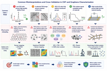
From Single-Technique Analysis to Multimodal Characterization: Recent Advances and Future Perspectives for Carbon Nanotubes and Graphene
3
Is Produced Water a Source of Lithium?
4
Environmental Sample Prep Workflow Optimization
5