Article
Spectroscopy
Spectroscopy
Sample Preparation–Free Micro ATR FT -IR Chemical Imaging of Polymers and Polymer Laminates
A new method allows samples to be measured "as-is" with direct contact with the ATR crystal.
The micro attenuated total reflectance (ATR) chemical imaging of polymers, in particular polymer laminates, typically requires significant pressure to ensure good sample-to-ATR crystal contact. For thin cross-sectioned materials, ensuring structural rigidity against this pressure requires significant sample preparation, such as resin embedding, cutting, and polishing. Such procedures are tedious, require overnight resin curing, and carry the added risk of cross-contamination. Presented here is a novel method of ultralow-pressure micro ATR Fourier transform infrared (FT-IR) chemical imaging that removes the need for any structural support and allows samples to be measured "as-is" (no embedding) with direct contact with the ATR crystal.
Polymer laminates are film structures consisting of two or more layers adhered together to make a structure. The polymeric materials forming these laminates have varying thickness (from a few micrometers to >100 µm), which can influence a variety of properties, including chemical, mechanical, and barrier (for example, impervious to oxygen or moisture) properties. To construct these materials, adhesive (tie) layers are often required between two adjacent and chemically incompatible layers. Typically, these incompatibilities are between materials with differing polarities, such as nylon and polyethylene. The adhesives usually have intermediate polarity or contain functional groups with an affinity to both polar and nonpolar sides and hence act as good binding material. Such adhesive layers can be very thin, ranging from ~2 µm to ~10 µm. Polymer laminates can range in complexity and thickness from only two layers to well over 10 layers (not including adhesive layers), with total cross-sectional thicknesses ranging from <50 µm to >200 µm. Polymer laminates can be used in a variety of applications ranging from food packaging to pharmaceutical packaging.
With ever-increasing manufacturing sophistication enabling the production of more complex and thinner laminate structures, the analytical challenges to ensure good product quality control, troubleshooting, or the reverse engineering of competitive products are also increasing in complexity.
The analytical tools available to analyze such laminates include a range of optical microscopy techniques, thermal techniques (such as differential scanning calorimetry), and various spectroscopic techniques.
In particular, Fourier transform infrared (FT-IR) microscopy has proven most useful for the analysis of polymer laminates. This suitability resulted from the core application of FT-IR spectroscopy for the identification and characterization of polymers in general, combined with the ability to obtain this information from small areas.
When applied to polymer laminate analysis, FT-IR microscopy is typically performed in transmission mode and requires that the total sampled thickness be within a certain maximum thickness limit, which is usually 10–20 µm for polymeric materials. To prepare thinly sliced polymer and polymer laminate materials at <15–20 µm presents some challenges. Often, dedicated (and often expensive) specialized cutting devices are required, such as microtomes. Even then, the cut samples are often difficult to handle because of curling or difficulties with static stick. To minimize these effects, samples can be embedded in resin and microtomed together within the resin support before cutting. This, unfortunately, adds another material with a complex IR spectrum to the sample. After the sample is cut, if it is flat, it can be placed in a sandwich between IR-transparent windows and sampled in transmission mode. Even still, because of sample front and backside inter-reflections, "fringing effects" can commonly be observed, which present themselves as a sinusoidal baseline.

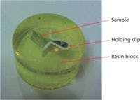
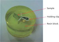
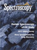
Figure 1: An example of a polymer film, held by clips embedded in a polished resin block.
With these issues and sampling preparation steps aside, transmission FT-IR microscopy is a relatively simple technique to obtain spectra from small areas. It does however suffer from one major limitation — spatial resolution is relatively poor, especially when compared to optical microscopy techniques. Typical spatial resolution limits are about 10–15 µm.
The use of micro attenuated total reflectance (ATR ) as a mode of analysis removes the requirement for a certain thickness, so samples no longer need to be thinly cut. However, because ATR requires intimate contact with the samples, there are still some important sample preparation requirements. Primarily, the sample must be flat and smooth to ensure that there is full and complete contact across the ATR measurement field of view (FOV). Additionally, and of paramount importance to the detection of ultrathin layers, micro ATR FT-IR microscopy provides a factor of four spatial resolution enhancement over transmission mode.
To ensure that complete and intimate contact is taking place, a degree of pressure needs to be applied between the sample and the ATR crystal. Many micro ATR imaging systems rely on indirect methods of ensuring good contact by using coarse pressure sensors, often with preset pressure levels. For naturally hard materials, this is typically not an issue. However, for delicate or thin unsupported (nonresin embedded) samples, such as polymer laminates that typically range from 50–200 µm in total cross-sectioned thickness, any attempt to apply even very slight pressure on laminate cross-sections will cause the laminate to buckle under the pressure. The inability to directly monitor the exact moment and quality of contact in most micro ATR imaging systems is also another factor that requires the use of higher pressures to ensure good contact.
Therefore, to avoid buckling or other structural distortions of delicate and thin samples under applied ATR pressure, it is mandatory to provide some degree of support. This is most commonly achieved by resin embedding of the sample, followed by cutting and polishing of the surface.
The process of resin embedding is tedious and time consuming (>12 h), consisting of the following typical steps:
- Cut a small piece of sample and place vertically in spring clamp.
- Place sample and clamp in mold and pour in resin to fully cover sample.
- Allow to cure (typically overnight).
- Cut top surface to expose sample cross section.
- Polish cut surface with successively finer and finer lapping paper (from 30 µm to 1 µm).
Cutting and polishing also poses the risk of introducing resin and polishing material contaminations onto the sample that could complicate the image and spectral interpretation.
After such samples are prepared and are embedded in resin, they are brought into contact with the micro ATR crystal and pressure is applied. Often, the levels of pressure applied (even at lower settings) are enough to produce indentations at the surface of the samples, potentially preventing the subsequent analysis of the sample with other analytical techniques. This technique is then potentially destructive.
This article will discuss a new approach that removes the need for resin embedding or any other sample support mechanism, thereby enabling delicate and thin samples to be measured "as is." The core of this capability lies in the ability to use two-dimensional focal plane arrays (FPAs) as the infrared detector, but most importantly, it is the "live micro ATR imaging" feature with enhanced chemical contrast that facilitates this capability.
Unlike linear-array IR detectors, FPAs provide an instantaneous 2D IR image view of the sample in real-time; linear arrays, because of their 1D nature cannot provide real-time IR image feedback. This "real-time" feedback provides sample contact feedback before any data collection.
However, having a 2D FPA alone does not provide enough contrast to determine the moment of sample contact with the ATR crystal. To overcome these issues we recently developed "live ATR imaging" mode, which significantly enhances the chemical contrast of the real-time FPA image, so the exact moment of sample contact can be visualized and followed as the sample contact is increased. This approach offers direct and real-time monitoring of the quality of contact (that is, the sample makes complete contact across the FOV), allowing for an extremely low pressure to be applied.
It is this extremely low pressure that now allows for delicate and thin samples to be mounted, cross-sectioned end on, without any sample support — that is, no more resin embedding.
Experimental
Sample Measurement Steps with "Live ATR Imaging"
As a demonstration of this capability, Figure 2 shows a commercial sausage wrapper with a total thickness of ~55 µm, three main layers, and two additional tie (adhesive) layers in between the main layers. The process of sample preparation is completed in only a few steps and requires only a few minutes.

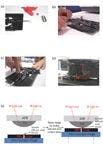

Figure 2: The five-step sample preparation process: (a) cut out small piece, (b) place the piece in the micro-vice, (c) cross-section the sample with a razor, (d) place the micro-vice with the sample on the microscope stage, and (e) raise the stage to make contact and collect data.
Instrumentation
The FT-IR imaging system consisted of an Agilent Cary 670-IR FT-IR spectrometer coupled to a Cary 620-IR FT-IR microscope with a 64×64 MCT FPA detector and a "slide-on" micro Ge ATR accessory attached to a 15×IR objective. The sample was mounted in a micro-vice from ST-Japan. Data were collected in ATR mode using the micro Ge ATR system at 4 cm-1 spectral resolution with 64 scans coadded (~2 min). This setup provides for a 70 µm × 70 µm FOV with a 1.1-µm pixel sampling size.
Results and Discussion
A side-by-side comparison of "standard ATR imaging" to monitor contact, compared with "live ATR imaging with enhanced chemical contrast" is shown in Figure 3. The upper series of images demonstrates that with standard ATR IR imaging it is impossible to directly detect and monitor the sample contact on the ATR system. However, in the lower series of images, the unique "live ATR IR imaging" has increased the chemical contrast significantly, thereby allowing the direct monitoring in real time of the sample contact as the sample is being raised and pushed against the crystal. This allows for the use of extremely small forces (pressure) on the sample, enabling cross-sectioned laminates to be measured directly, without the normal resin embedding. Even very thin samples with thicknesses of <50 µm can be directly measured with this approach.


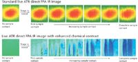
Figure 3: Comparisons of standard ATR IR images and live ATR imaging with enhanced chemical contrast show how the latter can detect the point of first contact and assess contact quality in real-time before any data collection.
A visual inspection of the sample using the FT-IR microscope binocular or internal visible camera (see Figure 4), reveals a polymer film containing three main polymer layers with two tie (adhesive) layers.

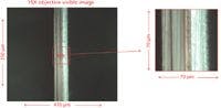

Figure 4: Full field of view visible image (left) with the thickness and chemical composition of the various layers identified, and a zoomed image (right) corresponding to the micro ATR FT-IR chemical image.
In Figure 5, a summary of the data is presented showing that five different layers have been identified with up to four chemical components. Three main polymer layers were observed and are clearly identified (via a spectral library search) as polyethylene (outer left and outer right layers) with the middle layer identified as nylon. These layers were determined to be 11, 16, and 20 µm in thickness, respectively. In addition, two distinct tie (adhesive) layers were observed. However, because of their very thin nature, some spectral or spatial mixing from the adjacent polyethylene and polyamide layers was detected. A simple interactive subtraction of these adjacent components allowed for an easy spectral library search. The left-hand side tie layer (between the polyethylene and nylon layers) was identified as a polyurethane at ~2 µm thick and the right-hand side tie layers (between the nylon and polyethylene layers) was identified as a pyrolyzate-based polyurethane at 5–6 µm thick. The spectra shown in Figure 5 from these tie layers are raw, unsubtracted spectra.

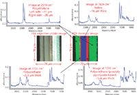
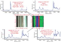
Figure 5: Zoomed visible image (left) corresponding to the micro ATR FT-IR chemical image field of view, and a red-green-blue false color image overlay (right) created from the three distinct chemical components using their unique IR absorbance bands (as indicated in the figure).
Conclusions
We have demonstrated for the first time the ability to measure thin cross-section multilayer films "as is" without any embedding in FT-IR ATR imaging mode using a novel "live ATR imaging with enhanced chemical contrast" methodology. This new technique provides for rapid analysis, from sample to chemical images in a few minutes (compared to 12–48 h for resin-embedded samples) and because it is nondestructive, it allows for multiple measurements from across the sample to be collected rapidly.
Additionally, the micro ATR design, in combination with the use of an FPA detector, provides a sample pixel size of 1.1 µm, with demonstrated abilities to measure adhesive layers as thin as 2 µm, providing high levels of detail and information to assist in the most complicated and difficult sample measurements.
This ultrasensitive ATR imaging technique with no sample preparation can be applied to many other sample types where resin embedding is difficult or impossible or where the sample must not be damaged, such as historic or artistic artifacts and delicate biological samples.
Dr. Mustafa Kansiz is an Imaging FT-IR Product Manager with Agilent Technologies, in Melbourne, Australia. Direct correspondence to: mustafa.kansiz@agilent.com


Newsletter
Get essential updates on the latest spectroscopy technologies, regulatory standards, and best practices—subscribe today to Spectroscopy.