
|Articles|June 1, 2019
- Special Issues-06-01-2019
- Volume 34
- Issue 6
Criteria for High-Quality Raman Microscopy
Five key qualitative factors–speed, sensitivity, resolution, modularity and upgradeability, and combinability–contribute to the quality of confocal Raman imaging microscopes. Using application examples, this article introduces modern Raman imaging and correlative imaging techniques, and presents state-of-the-art practice examples from polymer research, pharmaceutics, low-dimensional materials research, and life sciences.
Advertisement
In recent years, confocal Raman imaging and related techniques have become more and more popular in many fields of application such as materials science, pharmaceutics, life sciences, geoscience, food technology, and many others. The available Raman microscopes are focused on user-friendly and intuitive operation. Additionally, several key qualitative factors of confocal Raman imaging microscopes should be considered to guarantee clear and substantial results. In this article, the following five criteria–speed, sensitivity, resolution, modularity and upgradeability, and combinability–are explained, and factors that influence them positively or negatively are examined. On the basis of application examples, modern Raman imaging and correlative imaging techniques are introduced, and state-of-the-art practice examples from polymer research, pharmaceutics, low-dimensional materials research, and life sciences are presented.
It was 90 years ago that Chandrasekhara Venkata Raman and Kariamanickam Srinivasa Krishnan first documented "A New Type of Secondary Radiation," which then became known as the Raman effect (1,2). Raman spectroscopy is based on this effect, and it is used for qualitative and quantitative analysis of the chemical components and molecules of a sample. It is a nondestructive method that requires little, if any, sample preparation.
Nevertheless, Raman spectroscopy long remained a technique that was only performed in specialized laboratories. In recent years, however, it has been increasingly losing its outsider status. One reason for this is the development of the confocal Raman microscope, with which not only individual Raman spectra, but also complete images generated from thousands of spectra, can be acquired. Through continuous development, commercially available Raman microscopes are also becoming more user-friendly. For example, modern software interfaces guide the user through the Raman measurement and the subsequent data analysis.
There are several key factors that can be used as criteria for determining the quality of confocal Raman microscopes, which are explained as follows:
Speed
In the past, exposure times of minutes to hours were common for acquiring single Raman spectra, but today the process generally takes fractions of a second to less than one millisecond. In one second, more than 1000 Raman spectra can be recorded. Thus, a Raman image can be generated within a few minutes. To achieve this acquisition speed, the Raman imaging system should be equipped with optimized optics and an electron multiplying charge coupled device (EMCCD) camera.
High acquisition speeds are particularly important for measurements on sensitive and valuable samples in which the excitation energy must be as low as possible. Time-resolved investigations of dynamic processes can also benefit from rapid Raman spectral acquisition. Operating costs can also be reduced by shorter analysis times concurrent with increased data rates. Having a high system speed is also advantageous for time-critical work.
Sensitivity
The signal sensitivity of a system is critical for the quality of the results, and is especially important when weak Raman signals are to be detected.
To achieve the best possible sensitivity, a confocal beam path, such as using a diaphragm aperture, must be employed to eliminate light from outside the focal plane to increase the signal-to-noise ratio. The entire Raman imaging system should also be optimized for high light throughput. This includes a spectrometer that ensures throughput of over 70%, and is designed for measurements with low light and signal intensity. Charge-coupled device (CCD) cameras optimized for spectroscopy, which exhibit more than 90% quantum efficiency in the visible range, are most commonly used as detectors. Finally, the use of almost lossless photonic fibers ensures efficient light and signal transmission.
Resolution
The resolution of a Raman system comprises both spatial and spectral resolution. The spatial resolution includes the lateral resolution (x- and y-directions) and the depth resolution (z-direction). The spatial resolution is determined by the numerical aperture (NA) of the objective used and the excitation wavelength. In addition, a confocal microscope produces images with a higher contrast, because the background signal is reduced. The smaller the aperture of a confocal microscope, the higher its resolution. In a confocal Raman microscope, the lateral resolution is about 200–300 nm, and the depth resolution below 1 micrometer. A confocal microscope can also create optical sections from different focal planes, which can be used with transparent samples for depth profiles and 3D images.
Spectral resolution defines the ability of a spectroscopic system to separate Raman lines near one another. Symmetric peaks in the spectrum are ensured by a spectrometer design that operates free of coma and astigmatism. The grating used, the focal length of the spectrometer, the pixel size of the CCD camera, and the size of the aperture also affect the spectral resolution.
At room temperature, the width of the Raman lines is typically greater than 3 cm-1, but some applications (gases, low temperature, or stress analysis) may require significantly higher resolution (Figure 1).
Figure 1: Speed, sensitivity, and resolution are some of the characteristics that can be used to identify a high quality Raman microscope. These three characteristics should not be mutually exclusive. Ideally, the Raman imaging system should be configured in such a way that high-resolution images with a high signal-to-noise ratio can be acquired in a short period of time.
Modularity and Upgradeability
The introduction of Raman microscopy into laboratories puts new demands on commercially available systems. These requirements can sometimes appear contradictory: easy operation with diverse functionality, a wide range of applications with optimized sensitivity, low cost, and high performance. To offer users a Raman system tailored to their individual requirements, it is particularly important that systems have a modular design that can be adapted to new conditions through being reconfigured or upgraded. A system can be optimized for specific requirements by individually combining suitable lasers, filters, lenses, spectrometers, and detectors. With such a customized Raman imaging system, the user is able to obtain meaningful Raman images, perform 3D volume scans, and create depth profiles.
Combinability
Confocal Raman microscopy can be combined with other microscopy techniques. By using different methods and correlating the data, the user attains a more comprehensive understanding of the sample. Common examples of correlative microscopy techniques are Raman-atomic force microscopy (AFM), Raman–scanning near-field optical microscopy (SNOM), and Raman–scanning electron microscopy (SEM). To correlate the data of these disparate technologies, the exact same sample location must be examined by each approach. If different instruments are to be used, finding this sample location can be very difficult and time-consuming. This is made much easier with a hybrid system that combines the different analysis methods in one instrument so that the sample can remain in place during all measurements.
Applications
Some applications of correlative Raman microscopy are:
Raman and Profilometry
For Raman microscopy, most samples do not need to be treated, stained, or otherwise prepared prior to measurement. The combination of a confocal Raman microscope with a profilometer module for focus stabilization allows rough or inclined surfaces to be examined (3,4). During Raman analysis, the examination area is kept constantly in focus by the simultaneously acquired profilometry data. This also compensates for thermal shifts and enables long-term measurements. The application example in Figure 2 shows the analysis of a microstructured silicon sample. The chemical image of the Raman measurement was overlaid onto the topographic profile measurement.
Figure 2: Topographic Raman image of a silicon microstructure.
Raman and Fluorescence
Fluorescence microscopy has been a widespread imaging method for the analysis of biological cells and organisms for decades. Samples are stained with fluorescent dyes or organisms are genetically engineered to express fluorescent proteins. The fluorescence signal is usually much stronger than the Raman signal. Nevertheless, correlative Raman fluorescence measurements are possible with an appropriate system. Figure 3 shows a Raman fluorescence image of a live cell culture of eukaryotic cells. An inverted confocal Raman microscope was used to examine the cells in their aqueous cell culture medium in the Petri dish. The cell nuclei were stained with the fluorescent dye 4',6-diamidino-2-phenylindole (DAPI). An excitation wavelength of 532 nm was used for the Raman measurement. An image with 50 x 40 µm² and 150 x 120 pixels was acquired. A Raman spectrum was recorded at each pixel. The recording time was 0.2 s per spectrum. In the correlative Raman fluorescence image, the nuclei are shown in blue (recorded with fluorescence microscopy), the nucleoli in green, and the endoplasmic reticula in red (recorded with Raman microscopy). The corresponding Raman spectra are shown in the same colors.
Figure 3: Showing (a) correlative Raman fluorescence image of primate cells in a cell culture. Blue objects are nuclei recorded by fluorescence microscopy, red objects are endoplasmic reticula, and green circles are nucleoli recorded by Raman microscopy. (b) Raman spectra associated with the image.
Raman and AFM
The combination of Raman microscopy, which provides information about the type and distribution of molecules in a sample, and the high-resolution AFM technique, which determines the surface characteristics of a sample, enables the visualization of both chemical and morphological properties.
Here, the analysis of a 1:1:1 mixture of polystyrene (PS), 2-ethylhexyl acrylate (EHA) and styrene-butadiene rubber (SBR) is shown. For this, a correlative Raman–AFM microscope was used, in which Raman microscopy and AFM technologies are fully integrated.
The measurement with AFM in intermittent contact or alternating current (AC) mode documents the topography of the polymer mixture (Figure 4a). The simultaneously recorded phase image (Figure 4b) provides information on the viscosity and elasticity of the individual components of the polymer mixture. The confocal Raman image (Figure 4c) shows that PS (red) and EHA (green) are present separately. SBR (purple) partly mixes with EHA (mixture shown in blue). By correlating the Raman image with the AFM image, the chemical information can be linked to the structural information (Figure 4d).
Figure 4: Correlative, high resolution Raman-atomic force microscopy (AFM) image of a 1:1:1 mixture of polystyrene (PS), 2-ethylhexyl acrylate (EHA), and styrene-butadiene rubber (SBR). The image shows (a) the topography of the polymer mixture determined with AFM in the AC mode; with (b) the phase of the AFM image showing the fine structure of the compound. In (c) a color-coded, confocal Raman image is shown as generated from the Raman spectra, showing the distribution of the polymers: PS (red), EHA (green). SBR (purple), and SBR-EHA mixture (blue). In (d) a correlative Raman-AFM image is shown where the topography and distribution of the different polymers can be visualized.
Raman and SEM
Scanning electron microscopy (SEM) is a well-established method for structural surface analysis. By combining Raman imaging with SEM in a correlative microscope, it is possible to combine results of SEM structural analysis with chemical and molecular information from confocal Raman microscopy (5). The sample is placed in the vacuum chamber of the electron microscope. Both analysis methods are then carried out automatically at the same sample location. The obtained SEM and Raman images can then be superimposed.
In Figure 5, a structure several atoms in thickness comprised of graphene layers was analyzed by correlative Raman–SEM microscopy. The Raman image consists of 22,500 spectra with 50 ms recording time per spectrum. While in the SEM image the contrast between the substrate and the graphene flake is visible, in the Raman image the number of graphene layers and their different orientations can be analyzed. This is not possible with SEM alone.
Figure 5: Correlative Raman-scanning electron microscopy (SEM) image of a multilayer graphene flake. The different colors show folds and orientations in the graphene that can be identified by Raman spectroscopic analysis.
Raman Particle Identification and Characterization
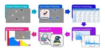
High-resolution investigations of particles are of great interest in many fields of application such as environmental science, pharmaceutical research, and many others. Combining a particle analysis tool with the fast, label-free, and nondestructive Raman imaging technique makes it possible to find, classify, and identify particles in a sample according to their size, shape and chemical characteristics. The physical and molecular attributes of the particles in a sample may be correlated and qualitatively and quantitatively evaluated. Figure 6 shows the results of particle analysis carried out on a cosmetic peeling cream sample. Figure 6a shows the overlay of an optical bright field microscope image with the corresponding confocal Raman image. Particles are identified according to their size and shape and further characterized by their molecular properties through confocal Raman imaging. The chemical analysis revealed anatase and boron nitride particles in an oil matrix (Raman spectra shown in Figure 6b). Further evaluation of the results determines the quantitative prevalence of the molecular sample components in the particles (Figure 6c) and also the distribution of chemical compounds correlated to particle size (Figure 6d). In extended analyses, the chemical characteristics of particles could also be linked to parameters such as area, perimeter, bounding box, Feret diameter, aspect ratio, equivalent diameter and many others. This illustrates the potential for comprehensive investigations of particles in many fields of application.
Figure 6: Particles in a cosmetic peeling cream sample; (a) the optical bright field image overlaid with the confocal Raman image; (b) the corresponding Raman spectra of the molecular components in the sample; (c) a pie chart of the quantitative compound distribution in the sample; and (d) the graphical representation of the correlation between chemical characteristics and particle size.
References
(1) C.V. Raman and K.S. Krishnan, Nature 121, 501 (1928).
(2) J. Toporski, T. Dieing and O. Hollricher, Eds., Confocal Raman Microscopy (Springer International Publishing, New York, New York, 2nd ed., 2018).
(3) A. Masic and J. C. Weaver, J. Struct.Biol. 189, 269–275 (2015).
(4) B. Kann, M. Windbergs, The AAPS Journal 15, 505–510 (2013).
(5) G. Wille, C. Lerouge, and U. Schmidt, J. Microsc. (Oxford, U.K.) 270, 309–317 (2018).
Damon Strom, Sonja Breuninger, Harald Fischer, Andrea Richter, Ute Schmidt, and Olaf Hollricher are with WITec GmbH, in Ulm, Germany. Direct correspondence to:
Articles in this issue
about 7 years ago
Vol 34 No s6 Raman Technology for Today's Spectroscopistsabout 7 years ago
Characterizing Microplastic Fibers Using Raman SpectroscopyAdvertisement
Related Content
Advertisement


Advertisement
Advertisement
Trending on Spectroscopy Online
1
How Do Molecular Analyzers Fit Into Digitalization and Closed-Loop Process Control?
2
Fujifilm, Horiba Unveil New Inline Raman System
3
Pathways in Spectroscopy: How to Succeed as an Applications Manager
4
Infrared and Near-Infrared Spectroscopy: Recent Advances and Environmental Applications (2022–2026)
5